
Valve timing controller, valve timing control method and engine control unit for internal combustion engine

a technology of valve timing control and internal combustion engine, which is applied in the direction of electric control, machines/engines, output power, etc., can solve the problems of deteriorating exhaust gas characteristics, fuel economy and operability

Inactive Publication Date: 2003-12-02
HONDA MOTOR CO LTD
View PDF2 Cites 21 Cited by
  • Summary
  • Abstract
  • Description
  • Claims
  • Application Information

AI Technical Summary

Benefits of technology

The present invention has been made to solve the problem as mentioned above, and its object is to provide a valve timing controller, a valve control method and an engine control unit suitable for use in a direct injection type internal combustion engine, which are capable of appropriately setting a valve timing in accordance with an engine load even in the stratified combustion mode.
This preferred embodiment of the engine control unit provides the same advantageous effects as provided by the corresponding preferred embodiment of the valve timing controller.

Problems solved by technology

The foregoing cam phase changing mechanism and profile switching mechanism, though contributing to the improvement on the exhaust gas characteristics and engine power, may experience problems as follows, if they are employed in the conventional direct injection type internal combustion engine.
Thus, if such a valve timing changing mechanism is simply combined in the conventional direct injection type internal combustion engine, a valve timing suitable for a load cannot be set in the stratified combustion mode, and as a result, the engine fails to ensure required engine power and internal EGR, resulting in deteriorated exhaust gas characteristics, fuel economy and operability.

Method used


Image

  • Valve timing controller, valve timing control method and engine control unit for internal combustion engine
  • Valve timing controller, valve timing control method and engine control unit for internal combustion engine
  • Valve timing controller, valve timing control method and engine control unit for internal combustion engine

Examples


Embodiment Construction

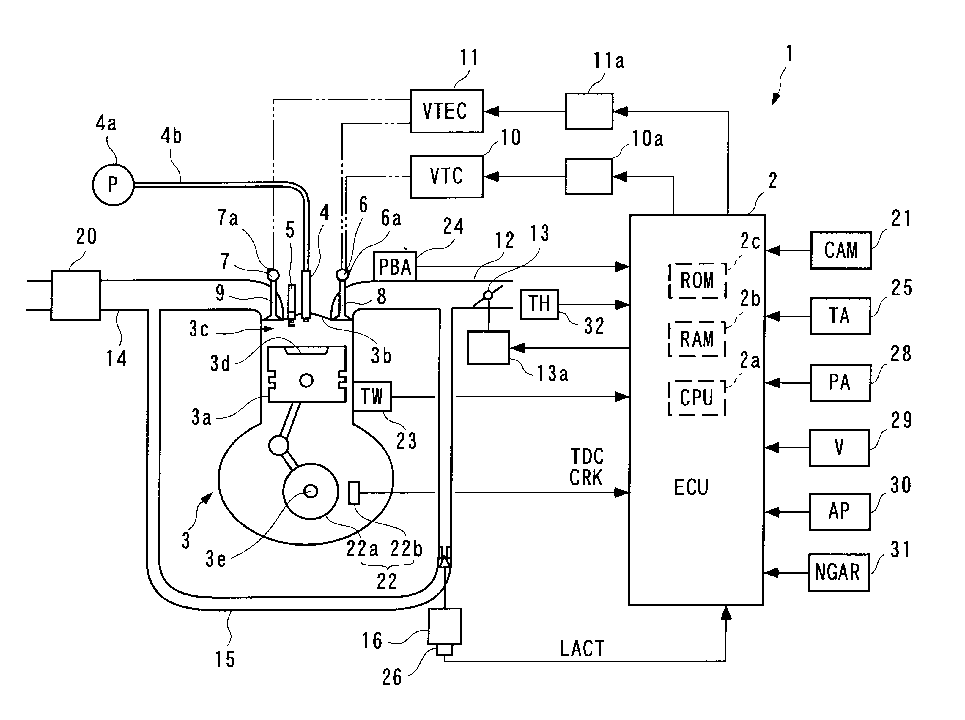
In the following, a valve timing controller for an internal combustion engine according to one embodiment of the present invention will be described with reference to the accompanying drawings. FIG. 1 generally illustrates the configuration of the valve timing controller according to this embodiment and an internal combustion engine in which the valve timing controller is applied.

The internal combustion engine (hereinafter referred to as the "engine") 3 is a straight four-cylinder DOHC type gasoline engine (only one cylinder is shown) which is equipped in a vehicle, not shown. A combustion chamber 3c is formed between a piston 3a and a cylinder head 3b of each cylinder, and a recess 3d is formed in a central portion of the top surface of the piston 3a. The combustion chamber 3c is provided with a fuel injection valve (hereinafter referred to as the "injector") 4 and an ignition plug 5. The injector 4 is directed to the recess 3d. Thus, the engine 3 is of a direct injection type whic...


PUM


Abstract

A valve timing controller for use in a direct injection type internal combustion engine is provided for enabling a valve timing to be appropriately set in accordance with a load on the engine even in a stratified combustion mode. The internal combustion engine has a valve timing changing mechanism for changing a valve timing of at least one of an intake valve and an exhaust valve so that it is operated in a combustion mode switched between a uniform combustion mode in which a fuel is injected into a cylinder during an intake stroke and a stratified combustion mode in which a fuel is injected into a cylinder in a compression stroke. The valve timing controller comprises a required torque determining unit for determining a required torque outputted by the internal combustion engine based on the engine rotational speed and accelerator pedal opening, and a valve timing determining unit for determining the valve timing in accordance with the required torque and the engine rotational speed.

Description

1. Field of the InventionThe present invention relates generally to a valve timing controller, a valve timing control method and an engine control unit for an internal combustion engine, and more particularly, to a valve timing controller, a valve timing control method and an engine control unit for an internal combustion engine which is equipped with a valve timing changing mechanism for changing a valve timing for at least one of an intake valve and an exhaust valve such that the engine is operated in a combustion mode switched between a uniform combustion mode in which a fuel injection is performed during an intake stroke and a stratified combustion mode in which a fuel injection is performed in a compression stroke.2. Description of the Prior ArtA conventional valve timing controller for an internal combustion engine of the type mentioned above is known, for example, from Laid-open Japanese Patent Application No. 7-301144. An internal combustion engine described in this document...

Claims


Application Information

Patent Timeline
Patent Type & Authority Patents(United States)
IPC IPC(8): F02D41/00F02D13/02F02B17/00F01L1/34F02B75/00F02B23/10F02D41/24F02D41/30F02B75/12F02M25/07F01L13/00F02D41/02F02D41/04F02F1/24
CPCF01L1/34F02B17/005F02D13/0219F02D13/0261Y02T10/123F02B23/101F02B2075/125F02D41/2422F02D41/3029F02D2041/001F02D2041/389F02D2250/18F02M25/0752F02M25/0756F02M25/0772Y02T10/18F01L2800/00F02M26/01F02M26/48F02M26/53Y02T10/12
Inventor OGAWA, KENKOMORIYA, ISAOEHARA, YASUNORI
Owner HONDA MOTOR CO LTD
Learn More