
Deep-set subsurface safety valve assembly

a safety valve and assembly technology, applied in the direction of sealing/packing, drilling pipes, wellbore/well accessories, etc., can solve the problems of affecting the local environment and its inhabitants, and affecting the safety of the subsurface safety valv

Inactive Publication Date: 2003-09-30
HALLIBURTON ENERGY SERVICES INC
View PDF17 Cites 61 Cited by
  • Summary
  • Abstract
  • Description
  • Claims
  • Application Information

AI Technical Summary

Problems solved by technology

Damage to the wellhead can cause a drastic interruption of normal well production operations.
In addition, damage may result in the leakage of hydrocarbons that pollute the surrounding environment and give rise to the danger of fire or explosion.
Leakage is particularly undesirable at wells located offshore or in urban areas, where the unintentional escape of oil and gas can have potentially disastrous consequences for the local environment and its inhabitants.
In the event that the wellhead control valve is damaged, for example, an abnormally rapid flow rate through the safety valve will be detected, signaling a potential leakage problem and triggering safety-valve closure.
When removable and reinstallation is required to service the TRSV the tubing length and type is a major factor in maintenance costs.
Maintaining a constant hydrostatic pressure over such a long run under adverse conditions can be problematic.
Batteries, however, run down over time and must be replaced, adding to the well-maintenance costs.
Although an umbilical does not have this disadvantage, it is subject to damage caused by other well equipment as it is moved in and out of the well.
Tubing length and type are even more important factors in the well costs associated with servicing subsurface safety valves in offshore wells.

Method used


Image

  • Deep-set subsurface safety valve assembly
  • Deep-set subsurface safety valve assembly
  • Deep-set subsurface safety valve assembly

Examples


Embodiment Construction

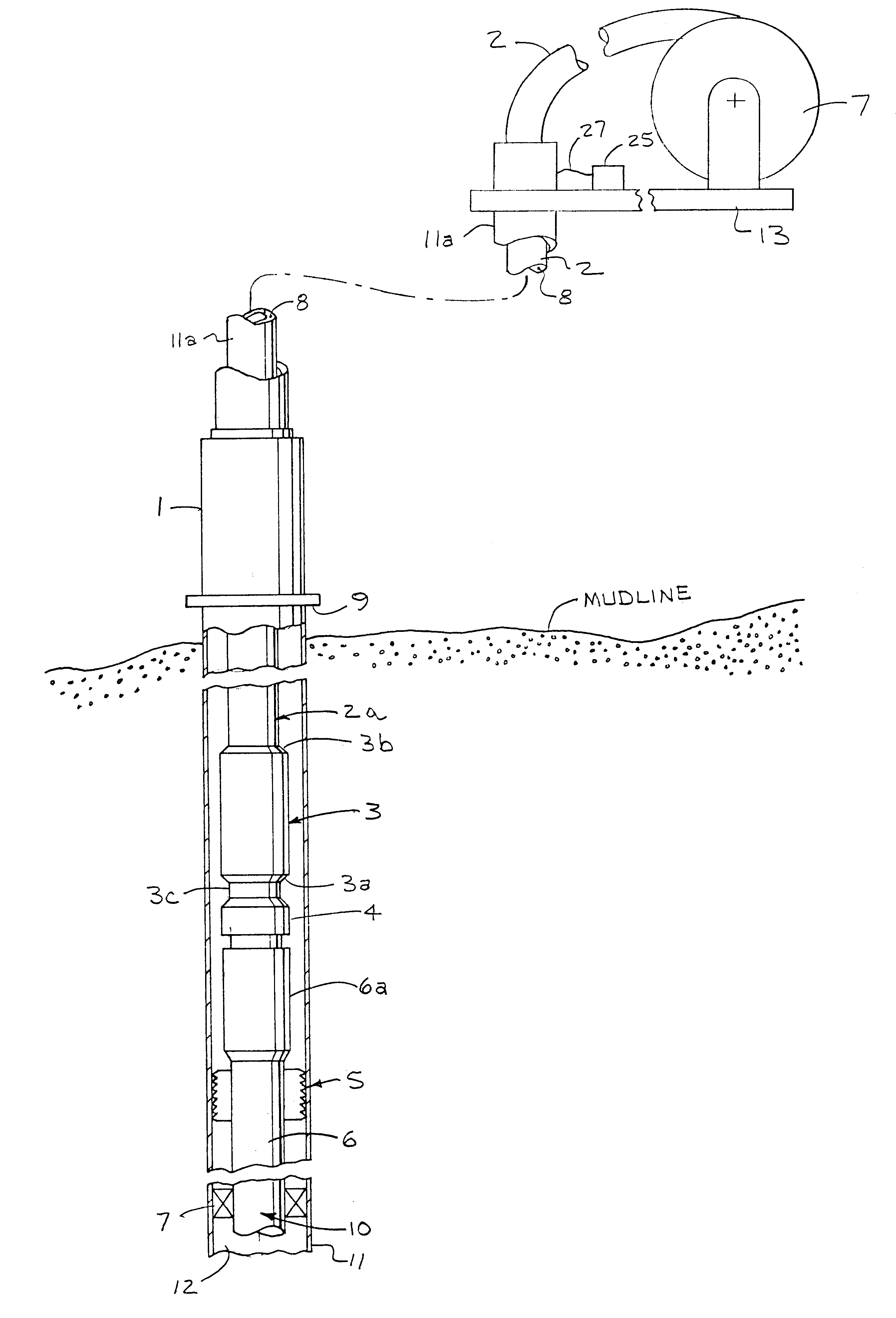
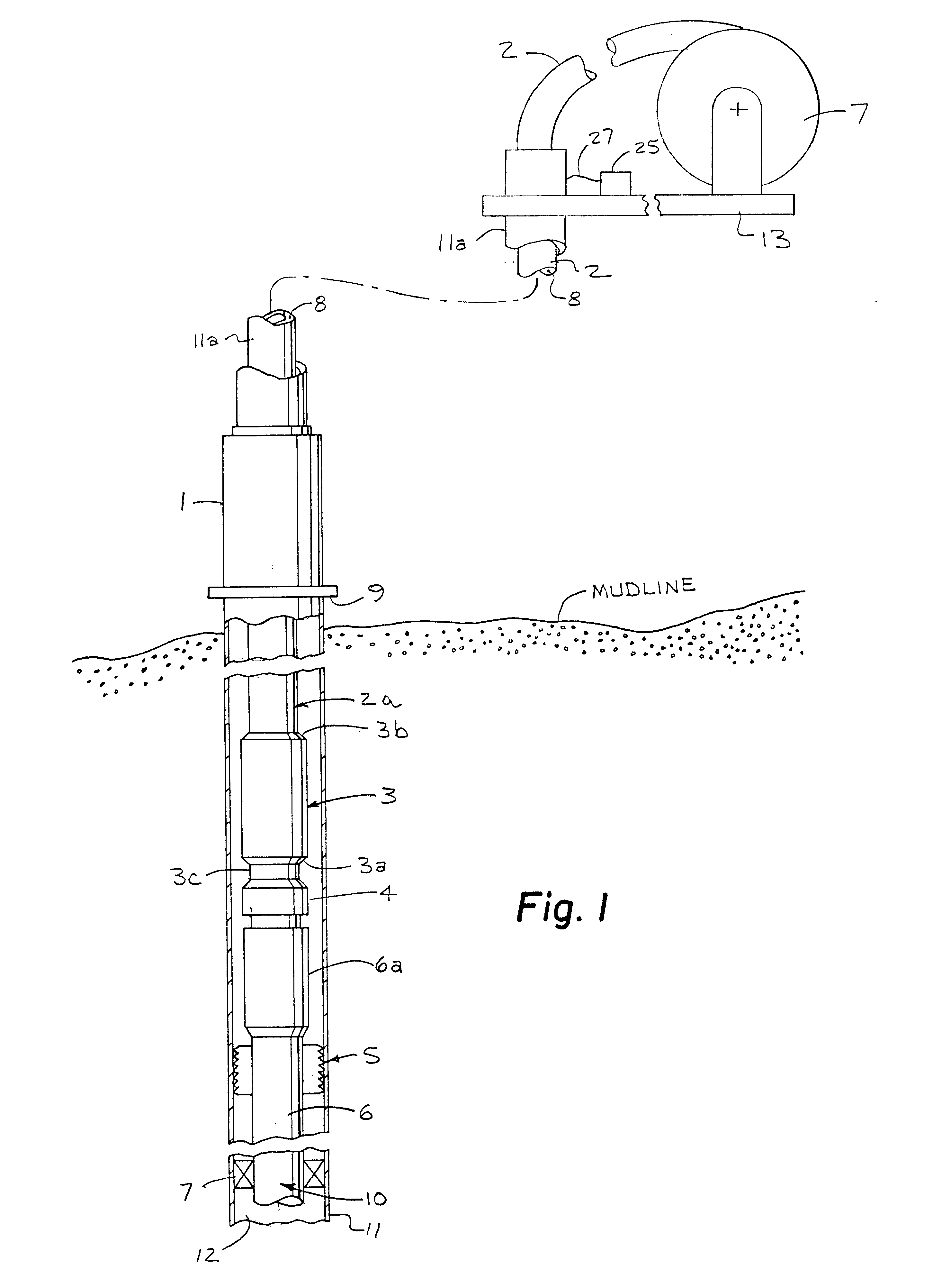
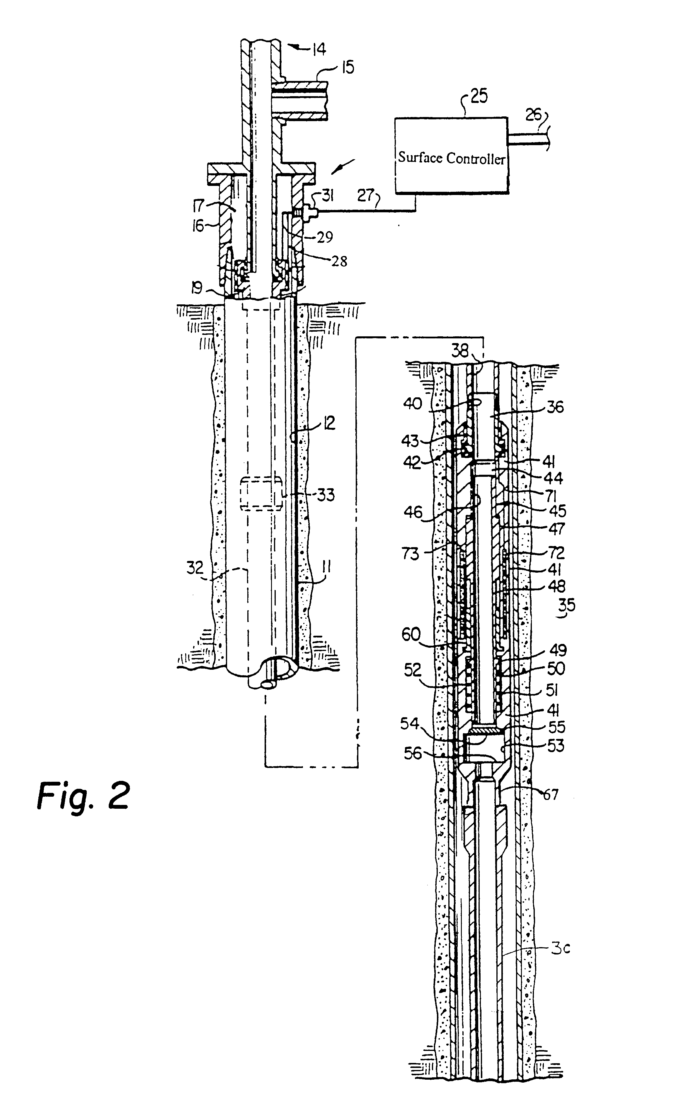
Referring now the drawings where like or corresponding reference characters are utilized through out the several views to refer to like are corresponding parts there is illustrated in FIG. 1 a simplified longitudinal schematic drawing of an embodiment of the safety valve and tubing latch assembly of the present invention shown in an offshore well environment. Offshore, is use herein to refer to wells drilled in a surface covered by water. Depicted in FIG. 1 is the uphole portion of a typical offshore well for producing hydrocarbons. The wellbore is identified by reference numeral 12 and is the cylindrical hole drilled in the formation and generally ranges from six to sixteen inches in diameter. Wellbore 12 is typically larger toward the mudline of the ocean floor, getting narrower in stages as it progresses downward. Wellbore 12 may be less than 1000 feet in depth, or well over 10,000 feet. Wellbore 12 is lined with casing 11, which is generally made of steel or a similar material. ...


PUM


Abstract

An apparatus and method for use in a cased well having a production tubing assembly installed in the well and terminating with a connection mechanism at a subterranean location. The apparatus and method utilizes a spoolable tubular assembly for installation extending into the well to the connection mechanism wherein the tubular assembly has a plurality of conductors formed connected to electrically operable valve, sensors and tubing latch in the tubular assembly. In the method the assembly is spooled into the well with the tubing latch being operated from outside the well through the tubing conductors to selectively connect and disconnect the assembly from the connector mechanism. Operating the salve and sensors from outside the well when the assembly is installed. The assembly tubing is preferably made of a non-conductive, and preferably composite material that enclosed at least one, and preferably a plurality of electrical conductors.

Description

Not applicableNot applicableREFERENCE TO MICROFICHE APPENDIXNot applicableThe present invention relates to petroleum-well downhole completion, and more specifically to a system and method providing a deep-set electrically controlled subsurface safety valve assembly.DESCRIPTION OF RELATED ARTOnce an oil or gas well has been drilled to total depth, and occasionally while drilling is still in progress, production of any hydrocarbons present in commercially available quantities can begin. Production is normally accomplished through a conduit, frequently referred to as production tubing, which is significantly smaller in diameter than the hole that has been bored into the earth. This allows for production at a satisfactory rate while also permitting installation of various types of ancillary equipment inside the wellbore. For example, the wellbore itself may be six to sixteen inches in diameter at the surface (where the well penetrates the earth), typically becoming incrementally smaller...

Claims


Application Information

Patent Timeline
Patent Type & Authority Patents(United States)
IPC IPC(8): E21B17/00E21B34/06E21B23/02E21B17/02E21B23/00E21B34/00
CPCE21B17/003E21B17/026E21B23/02E21B34/066E21B2034/005E21B2200/05
Inventor POWERS, JODY
Owner HALLIBURTON ENERGY SERVICES INC
Learn More