Static metal gasket and method of manufacturing it

Inactive Publication Date: 2003-09-16
SN DETUDE & DE CONSTR DE MOTEURS DAVIATION S N E C M A
View PDF17 Cites 20 Cited by
  • Summary
  • Abstract
  • Description
  • Claims
  • Application Information

AI Technical Summary

Benefits of technology

The invention thus provides a metal static gasket of design that is simpler than that of the gaskets that have been developed in the prior art, but which presents sealing performance that is equivalent or better. In particular, the shape of the profile of the gasket of the invention presents dimensional characteristics that are adapted to the presently-existing housings for receiving gaskets of larger profile. With smaller profile, the gasket of the invention presents usable restitution that is equiva

Problems solved by technology

Although such gaskets present characteristics that are satisfactory concerning performance and lifetime, they are nevertheless relatively difficult to manufacture because of

Method used


Image

  • Static metal gasket and method of manufacturing it
  • Static metal gasket and method of manufacturing it
  • Static metal gasket and method of manufacturing it

Examples


Example

The gasket described as an embodiment in the present description is of small size. Nevertheless, the invention also applies to gaskets of greater dimensions and larger size, in which case the performance of the gasket will be better than that described in the present description.

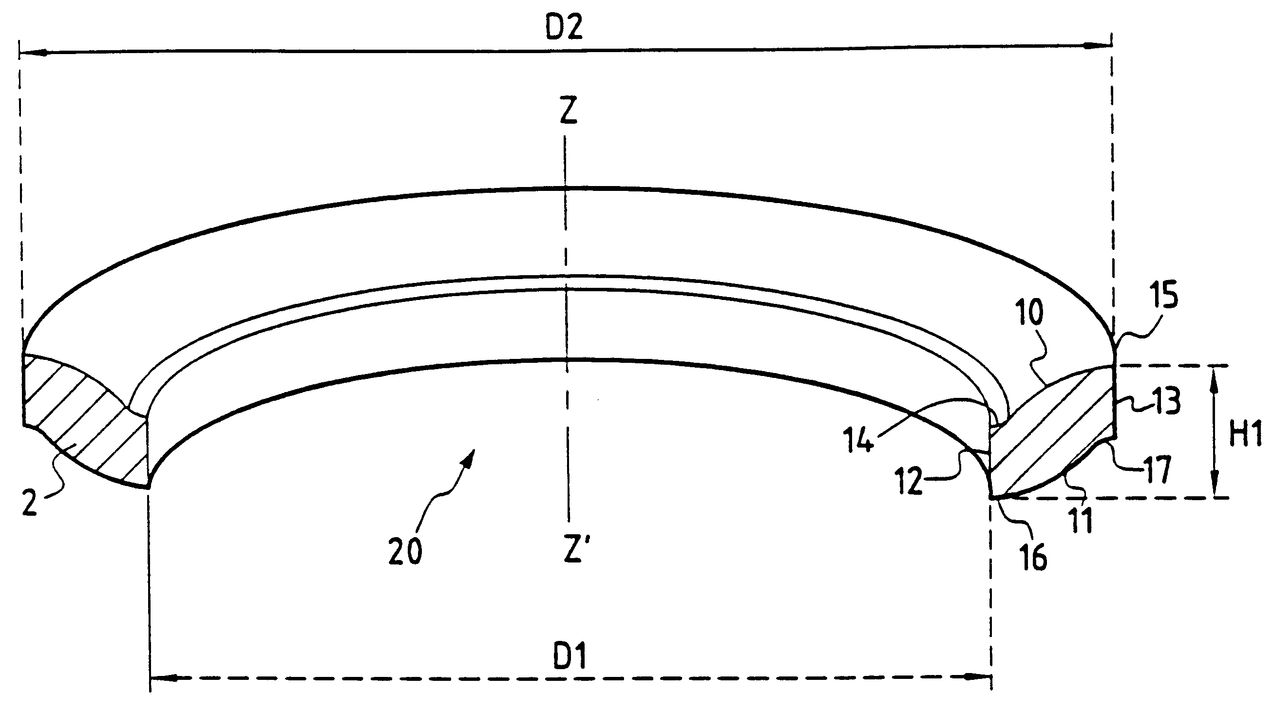
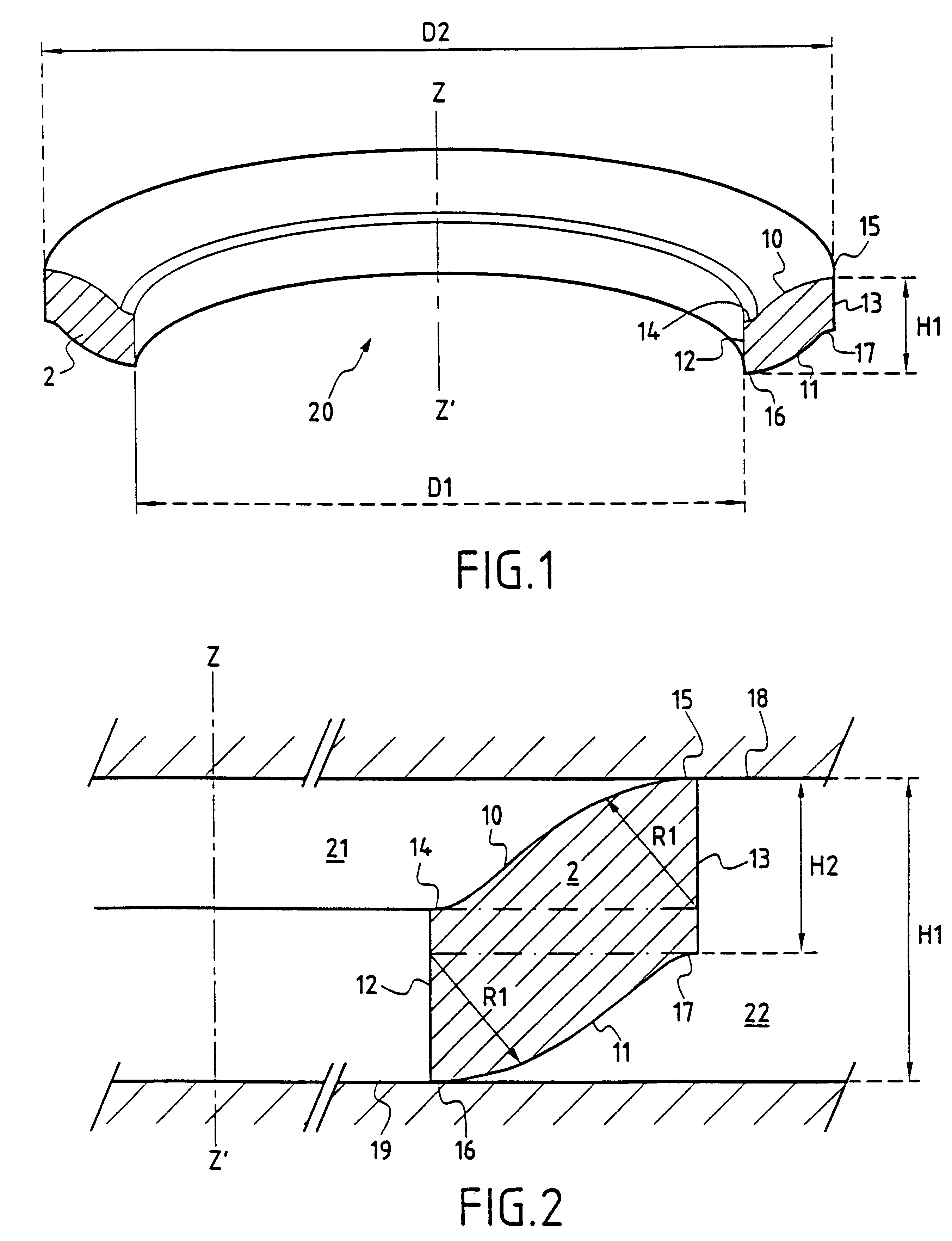
FIG. 1 shows the general appearance of a gasket 20 of the invention which comprises an annular body 2 about an axis ZZ', the body being in the form of an upward undulation going from its inside circumference towards its outside circumference, so that the gasket 20 thus defines an elongated S-shape in axial half-section (FIG. 2). In the drawings, a gasket 20 is shown whose undulation goes up from the center towards the periphery of the gasket. Nevertheless, the invention applies equally well to embodiments in which the annular body presents an undulation that goes down from the inside circumference towards the outside circumference of the gasket.

The gasket 20 shown in FIG. 1 is intended to provide internal an...


PUM


Abstract

The metal static gasket forms an annular body about an axis ZZ'. The profile of the gasket in axial half-section presents an elongated S-shape and comprises a lateral first portion defining the inner peripheral surface of the gasket, a lateral second portion defining the outer peripheral surface of the gasket, said lateral first and second portions being offset from each other along the direction of the axis of the gasket. The gasket also presents a curved third portion of undulating shape having a substantially rectilinear first contact region at one of its ends, and a curved fourth portion of undulating shape having a substantially rectilinear second contact region at one of its end extending perpendicularly to the axis of the gasket in such a manner that the gasket provides sealing between two flanges solely by means of the axial pressure exerted by the flanges.

Description

The present invention relates to a metal static gasket forming an annular body about an axis ZZ'.The invention relates more particularly to gaskets for providing sealing under very difficult conditions of use. Such gaskets can withstand temperatures that are very high or very low, and fluid pressures that are extreme, and they can also withstand large mechanical forces.PRIOR ARTHigh performance static gaskets used in such environments are already known, in particular from documents FR 2 726 879 and FR 2 757 923.Gaskets of that type all rely on the same principle: deformation of a channel-section profile.FIG. 5 shows an example of a prior art channel-section gasket 40. The gasket 40 comprises an annular body 47 about an axis ZZ', which body is extended laterally by lips 42 and 43 which are themselves associated with end portions 44 and 45 that define the contact surfaces of the gasket 10. Sealing is achieved by compressing the end portions 44, 45 between two flanges (not shown). Prof...

Claims


Application Information

Patent Timeline
IPC IPC(8): B21D53/16B21D53/20F16J15/08
CPCB21D53/20F16J15/0887
Inventor PYRE, ALAIN
Owner SN DETUDE & DE CONSTR DE MOTEURS DAVIATION S N E C M A
Why Eureka
Try Eureka