
Water immersion detecting circuit

a detection circuit and water immersion technology, applied in the direction of circuit inspection/indentification, liquid/fluent solid measurement, instruments, etc., can solve the problem of false detection when dew covers the electronic uni

Inactive Publication Date: 2003-08-05
KEIHIN CORP +1
View PDF7 Cites 32 Cited by
  • Summary
  • Abstract
  • Description
  • Claims
  • Application Information

AI Technical Summary

Problems solved by technology

However, in the conventional water immersion detecting circuit, since the sensor electrode pads are mounted on the printed board in such a way that they are adjacent and opposite to each other, false detection would be made when dew covers the electronic unit.

Method used


Image

  • Water immersion detecting circuit
  • Water immersion detecting circuit
  • Water immersion detecting circuit

Examples


Embodiment Construction

With reference to FIGS. 6 to 8, an example of a water immersion detecting circuit according to the invention will be described, in which the circuit is incorporated into an electronic circuit for driving an automotive power window. The water immersion detecting circuit incorporated into the electronic circuit may be of any type disclosed as the first to fifth embodiments of the invention or any other type defined within the scope of the present invention.

In this example, a water immersion detecting circuit according to the present invention is incorporated into the electronic unit so as to prevent false detection of the electronic circuit (electronic unit) when immersed into water as well as to prevent the automotive window from being unintentionally open or closed.

Referring now to FIG. 6, the driving circuit of the automotive power window will be described. The driving circuit includes a first line L1 connected to a power source 61 such as a 12-volt onboard battery (not shown), a s...


PUM


Abstract

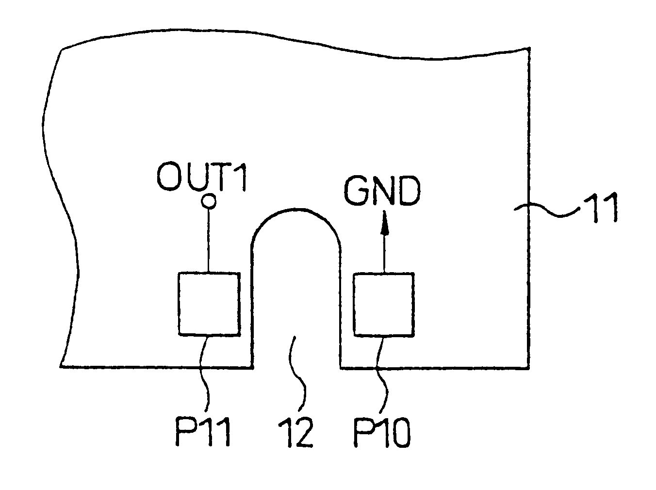
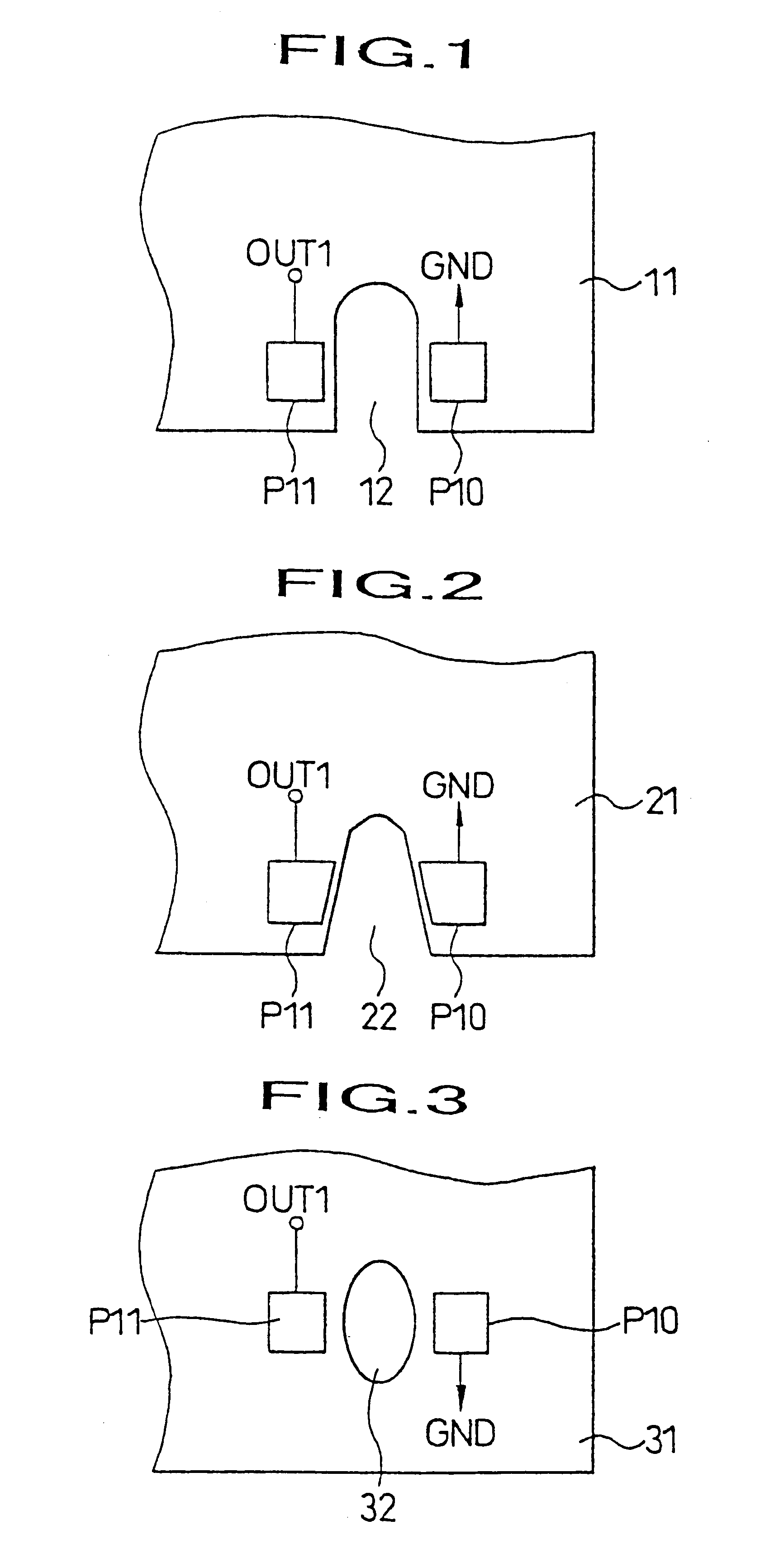
The object of the invention is to provide a water immersion detecting circuit, which is free from false detection and is stable and highly sensitive in operation. There is provide a water immersion detecting circuit provided on a printed board 11 of an electronic unit and used for detecting water immersion of the electronic unit based on a change of resistance generated between a pair of sensor electrodes for detecting water immersion P10, p11, wherein the pair of sensor electrodes P10, P11 are positioned opposite to each other on the printed board 11, and a U-shaped slit (opening) 12 is formed between the sensor electrodes P10, P11.

Description

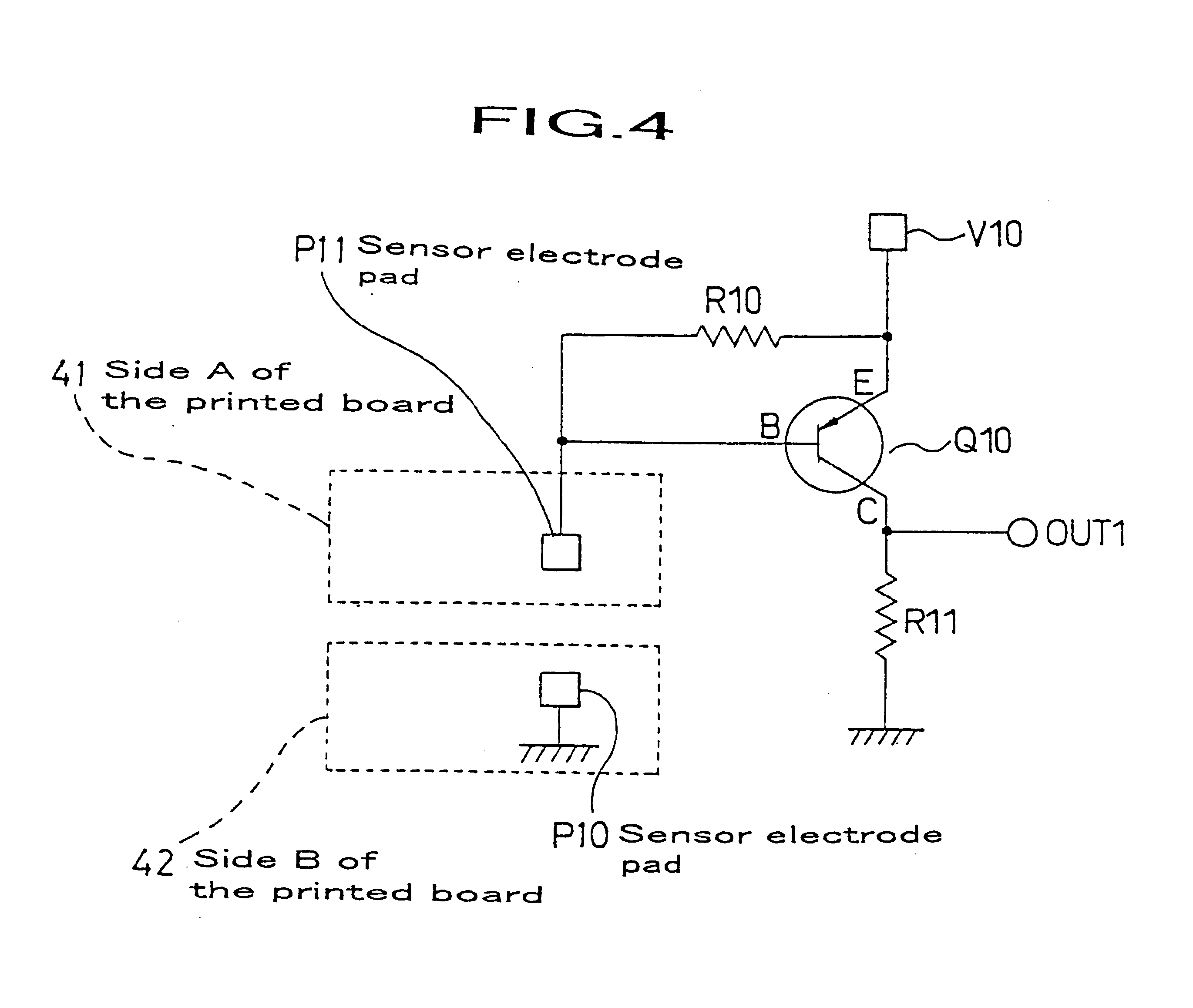
1. Field of the InventionThe present invention relates to a water immersion detecting circuit which is provided on a printed board of an electronic unit and is used for detecting water immersion of the electronic unit based on a change of resistance generated between a pair of sensor electrodes for detecting water immersion. More particularly, the present invention relates to a water immersion detecting circuit which is characterized by arrangements of the sensor electrodes, and which is highly resistant to malfunction due to dampness and dew condensation, and further which actuates accurately when the electronic unit is immersed in water.2. Prior ArtIn a related prior art technology, the following circuit is typically used. FIG. 9 is a circuit diagram of the conventional water immersion detecting circuit, in which P10 and P11 designate sensor electrode pads for detecting water immersion, Q10 designates an output transistor for detecting water immersion, R10 designates a resistor fo...

Claims


Application Information

Patent Timeline
Patent Type & Authority Patents(United States)
IPC IPC(8): G01F23/24H05K1/02
CPCG01F23/243H05K1/0268
Inventor KASAHARA, MAMORUNOMURA, SHIGEOKONDO, ICHIROYAMAOKA, KOUJIKAWAMATA, SEIJIYU
Owner KEIHIN CORP
Learn More