Hydraulic fastening of components

Inactive Publication Date: 2003-07-08
KEECH CASTINGS AUSTRALIA
View PDF6 Cites 13 Cited by
  • Summary
  • Abstract
  • Description
  • Claims
  • Application Information

AI Technical Summary

Problems solved by technology

Withdrawal of the force may cause retraction of the or each protrusion into the body member.

Method used


Image

  • Hydraulic fastening of components
  • Hydraulic fastening of components
  • Hydraulic fastening of components

Examples


Embodiment Construction

)

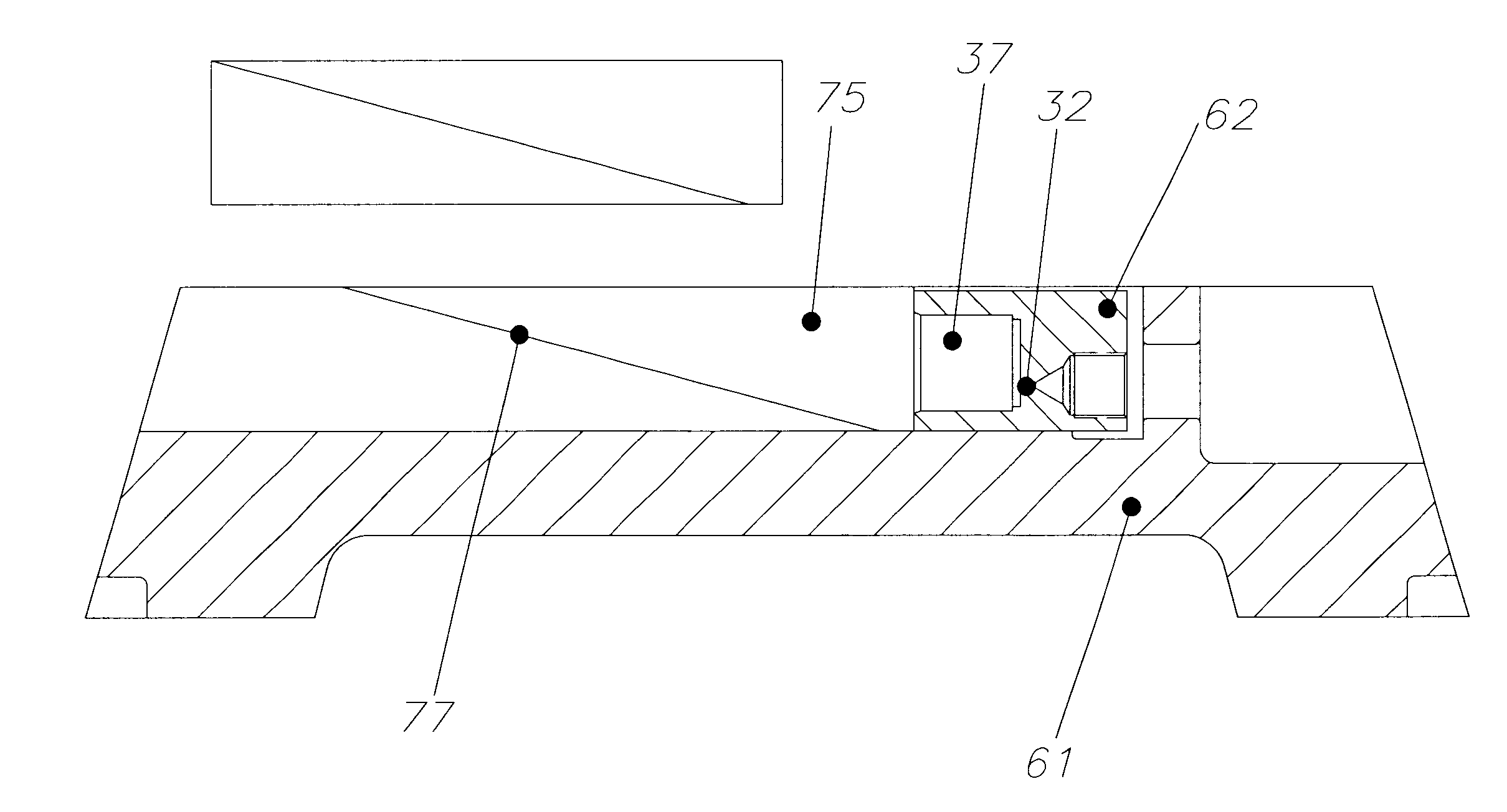
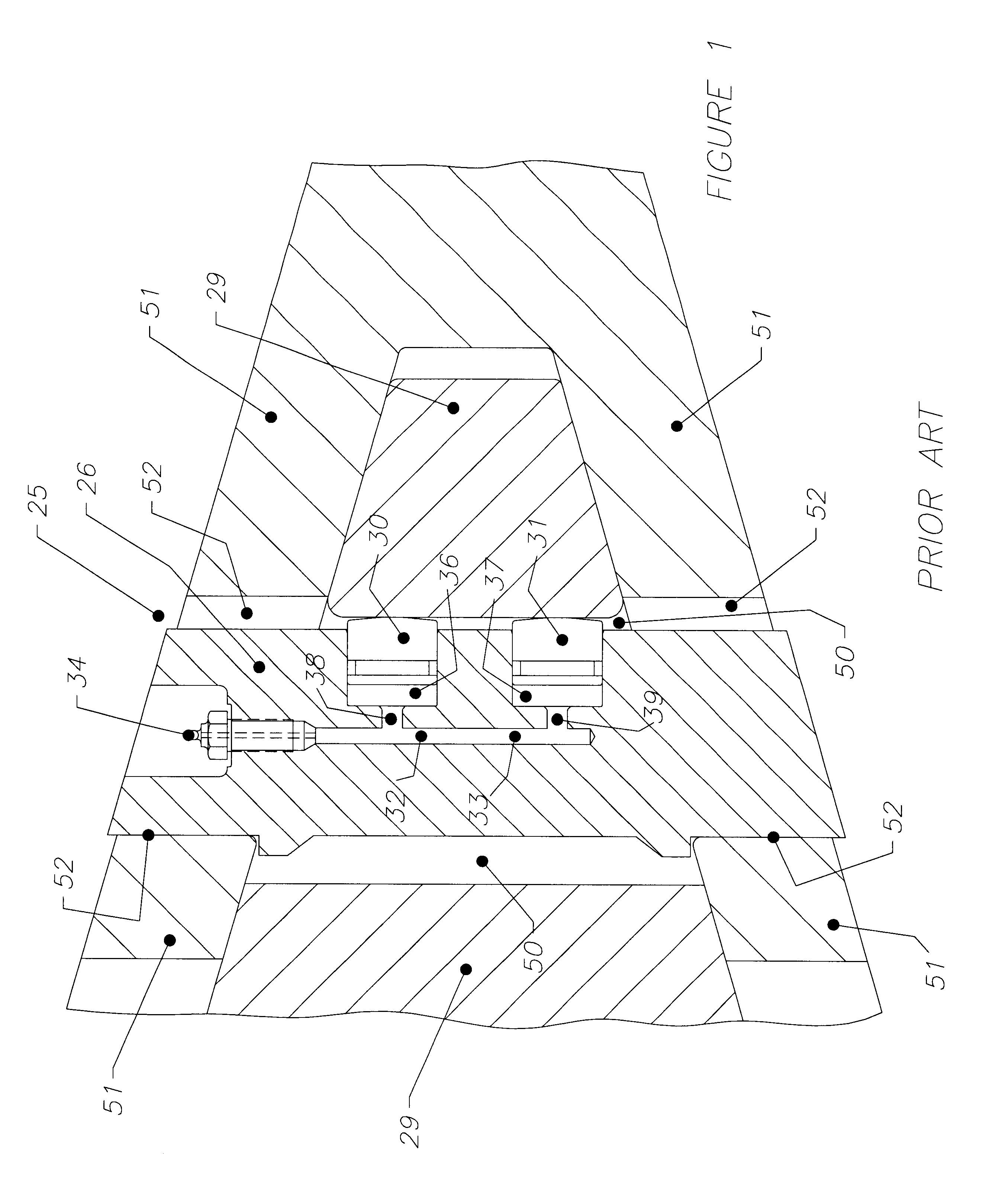
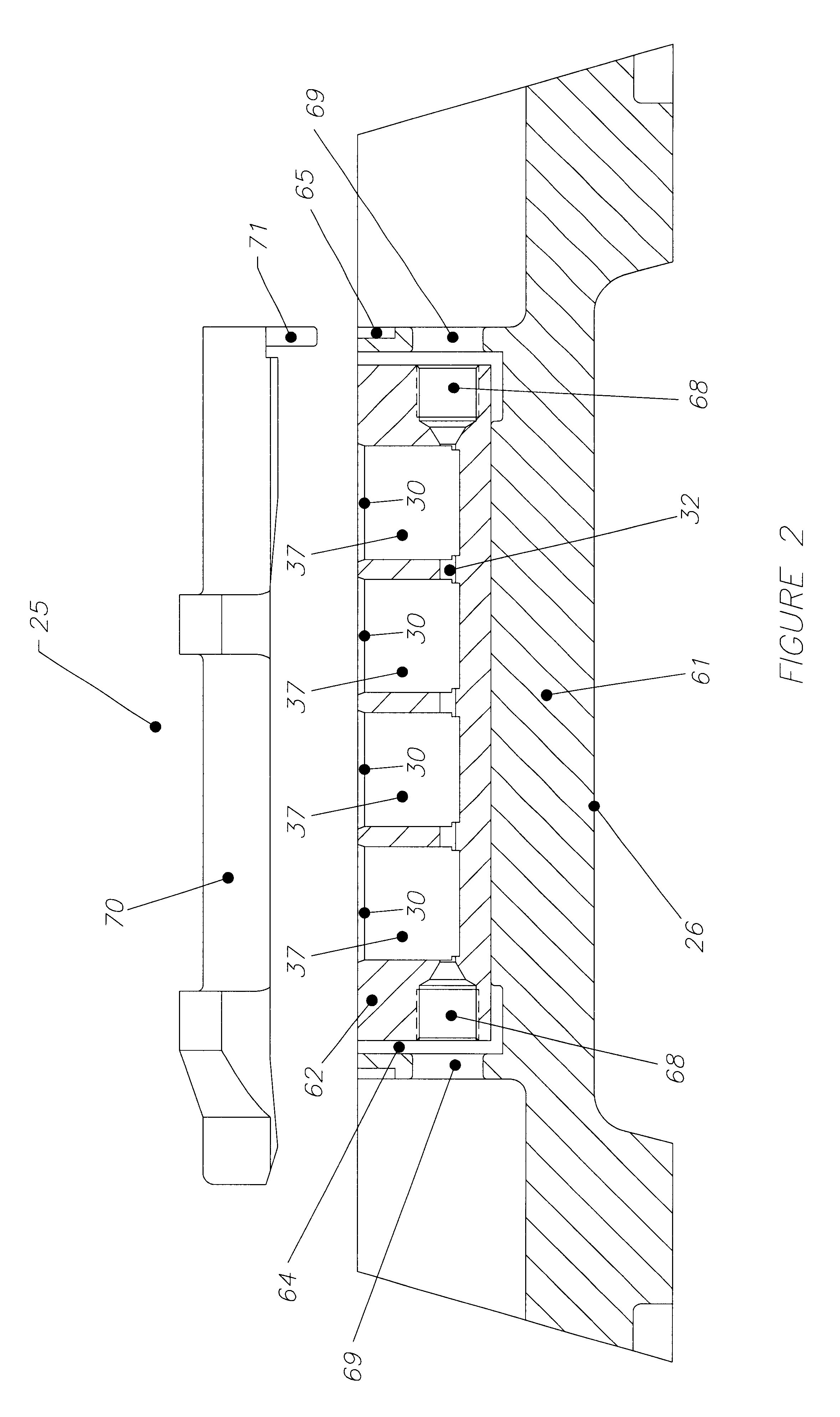
Referring to FIG. 1. there is shown a cross sectional view of a known fastening assembly 25 as disclosed in Australian Patent No. 673946.

Assembly 25 generally comprises a substantially elongate body member 26 adapted to be inserted substantially within orifices or cavities of the pair of components. As shown a first of the components is an outwardly projecting member 29 provided on a bucket or other component of an earthmoving or mining equipment. Component 29 is provided with an orifice 50 transversely therethrough. The second component is a complementary shaped component 51 which is adapted to be secured to the first component 29. The second component 51 is adapted to substantially surround the projecting member 29, and is also provided with an orifice 52 therethrough. The orifice 52 is adapted to substantially coaxially align with the orifice 50 such that the fastening device may be inserted therein. As will be seen, when the first component 29 is substantially aligned with the ...


PUM


Abstract

A hydraulic fastening device for securement of two components, each component having an orifice at least partly therethrough adapted to be coaxially aligned, the fastening device including a body member adapted to be inserted within the orifice of each component when coaxially aligned. The body member includes a main body section and a hydraulic manifold section with a fluid conduit within at least the manifold section and containing a fluid therein. The device further includes at least one moveable protrusion in fluid contact with the fluid, adapted to protrude from the manifold section; and control means to control the movement of each protrusion means. The arrangement is such that, upon operation of the control means, each protrusion is moved between a protruding position and a retracted position and when in the protruding position, the two components are adapted to be fastened together.

Description

The present invention relates to hydraulic fastening systems, device and method, and in particular to such which are useful, for example, in the mining or earthmoving industry for attaching teeth or wear plates to bucket drag lines of such implements and the like.The present invention is however useful for attaching any two components together which might normally be joined by some form of mechanical joining mechanism, such as bolts, screws, or welds.DESCRIPTION OF THE PRIOR ARTIn applicant's Australian Patent Specification No. 673946 there is disclosed a hydraulic fastening device for securement of two components together. Each component has an orifice or cavity at least partly therethrough which are adapted to be substantially coaxially aligned. The device includes an elongate body member adapted to be inserted within the orifice or cavity of each component when coaxially aligned. A fluid conduit is disposed within the body member and contains a fluid therein. There is further pro...

Claims


Application Information

Patent Timeline
Patent Type & Authority Patents(United States)
IPC IPC(8): E02F9/28F16B1/00
CPCE02F9/2841F16B1/005Y10T403/7064Y10T403/22Y10T403/7062Y10T403/76F16B2200/89
Inventor KEECH, GARTH ALEXANDERKEECH, DAVID KIM
Owner KEECH CASTINGS AUSTRALIA
Why Eureka
Try Eureka