
Accounting system in a communication network

a communication network and accounting system technology, applied in the field of communication devices, can solve the problems of imposing technical challenges, affecting the billing process, and the evolution of fairly complicated charging strategies

Inactive Publication Date: 2003-06-10
BRITISH TELECOMM PLC
View PDF32 Cites 68 Cited by
  • Summary
  • Abstract
  • Description
  • Claims
  • Application Information

AI Technical Summary

Benefits of technology

Several advantages are achieved by the distribution of the account storage operation to the user apparatus. Firstly, data storage becomes more distributed, and hence the bottlenecks associated with storage of vast amounts of data centrally with the telecommunications suppliers (as at present) are reduced. Thus, this aspect of the present invention provides the technical benefits of parallel data processing.
There are also secondary benefits, since the customer is more easily able to rely upon accounting data which has been stored by his own apparatus, and is able also to process the stored data for his own purposes (for example, further distribution or charging of the cost).
According to a further aspect of the invention, the same technical principles may be applied within a network, to distribute the billing and accounting within the network rather than centralising it as at present.
This aspect of the invention renders it possible to select between a very large number of different services which may be available in future via telecommunications media.
Other aspects and embodiments of the invention are as described or claimed hereafter, with advantages that will be apparent from the following.

Problems solved by technology

On the other hand, telecommunication companies have historically charged for network usage, and have evolved fairly complicated charging strategies which differentiate between local and national calls, calls at different times of day, and so on.
At present, the problem of charging communications users is a formidable technical challenge.
It will be apparent that the cost of billing is substantial.
It seems likely that the cost and required complexity of billing systems will continue to increase in future, with the provision of ever wider ranges of telecommunications products and services and the proliferation of special rates and tariffs.

Method used


Image

  • Accounting system in a communication network
  • Accounting system in a communication network
  • Accounting system in a communication network

Examples


first embodiment

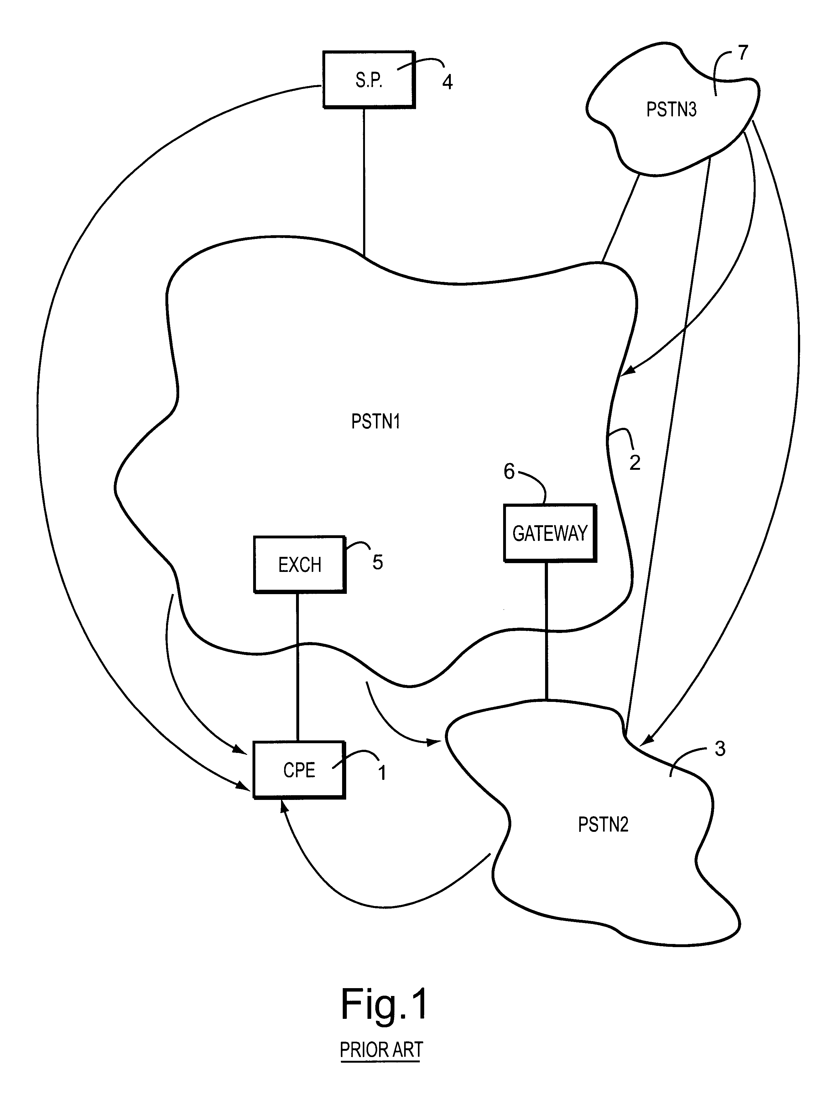
Referring to FIG. 1, in a telecommunications system (for example, the telecommunications system of the United Kingdom), customer premises equipment 1 (for example a telephone or a computer terminal incorporating a modem) is connected to a first pulse switch telephone network (PSTN) 2, and (via the network 2) to a second public switch telephone network 3. Via the networks 2, 3 the customer terminal 1 is connected to a service provider 4 (for example a database host).

With the PSTN 2, the customer terminal 1 is connected to an exchange 5, which is connectable to a gateway 6 linking to the second PSTN 3. A foreign telephone network 7 may be accessed from the customer terminal 1 via the first or second networks 2, 3.

In FIG. 1, straight lines indicate physical interconnection between apparatus, and curved arrows indicate billing flows. Typically, the operator of the first network 2 sends the customer 1 a quarterly or, in generally, periodic bill for his usage of the network. The operator ...

second embodiment

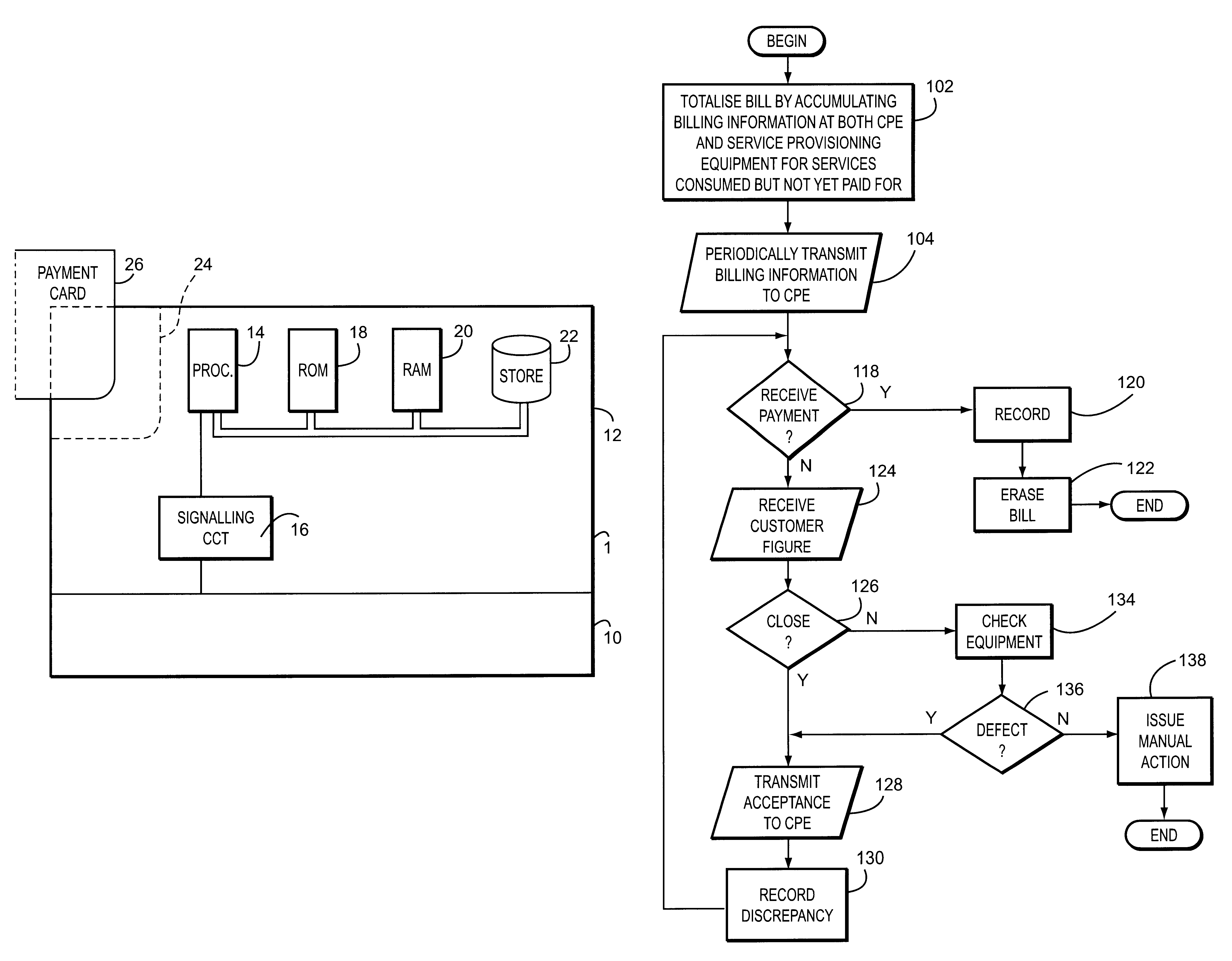
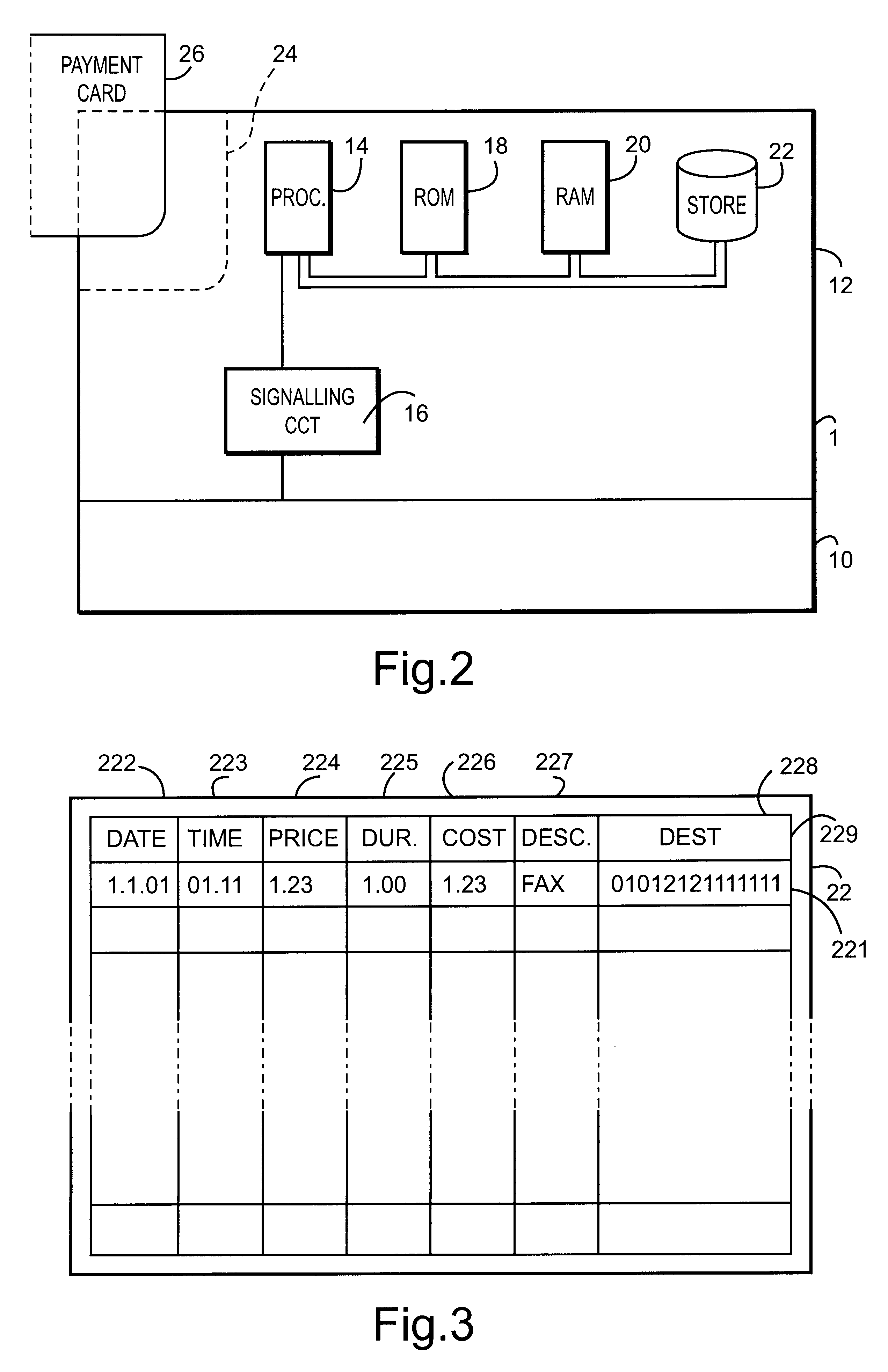
In this embodiment, a communications network is divided into a hierarchy of networks. Referring to FIG. 7, plurality of customer terminal apparatus 1a, 1b, 1c (each comprising, for example, a computer workstation equipped with a modem) are each provided with a corresponding accounting device 12a, 12b, 12c respectively, of the type illustrated in FIG. 2, the processor 14 and memory 18, 20 thereof being comprised by the CPU and memory of the work station, and the signalling circuit 16 thereof being comprised by the modem of the work station. The terminals 1a-1c are each connected to a Local Area Network (LAN), over which they communicate for example in TDM fashion. The LAN 50 has a gateway unit 52 for connection to a wide area network (WAN) 60. The wide area network 60 has, in turn, a gateway unit 62 for connection with a still wider network 72, such as a metropolitan area network (MAN) or information superhighway (e.g. the INTERNET) or a telecommunications network.

Referring to FIG. 8...

third embodiment

In the preceding embodiments, accounting apparatus was provided as part of the customer equipment, and the reconcilation was performed at the customer equipment. In the present embodiment, additionally or alternatively, a record of the call is made on apparatus which is independent of either the customer of the supplier, and is accessed either for confirmation of the reconciliation performed by the customer, or for the purpose of performing reconciliation of the amount payable instead of the customer.

Referring to FIG. 9, a network 53 (which may, for example, be an optical transmission network utilising wavelength division multiplexing and operating under asynchronous transfer mode (ATM) or synchronous digital hierarchy (SDH) transmission protocols) has an accounting station 54. The network 53 and accounting station 54 may be as described in the preceding embodiment, for example. Connected to the network is customer equipment 1a. Also connected to the network 53 is an independently o...


PUM


Abstract

A communication system includes a communication utilizing apparatus connectable to a communications network and service provision apparatus for making services available to the communications utilizing apparatus. An accounting device is associated with the communications utilizing apparatus and includes a digital data storage device arranged to store details of the receipt of services by the communications utilizing apparatus a signalling circuit arranged to receive, via the communications network, signals indicating a payment due in respect of services provided by the service provision apparatus, and a comparison device arranged to compare the received indications with data derived from the stored details.

Description

1. Field of the InventionThis invention relates to communication apparatus, and more particularly to communications apparatus for supplying and acquiring products and services from one or more suppliers of communications services or services offered over communications channels.The invention is chiefly, but not exclusively, concerned with the supply of telecommunication services to a customer from one or more telecommunications suppliers.2. Related ArtMore particularly, the present invention is primarily concerned with the communication or billing or charging information. At present, different suppliers of telecommunications services charge on different bases. Suppliers of data network services (e.g. local area networks) often charge on a fixed rate basis, without taking any account of the amount of usage at the network. This makes accounting extremely simple. On the other hand, telecommunication companies have historically charged for network usage, and have evolved fairly complica...

Claims


Application Information

Patent Timeline
IPC IPC(8): G07F17/00G07F17/16G07F7/08G07F7/00H04M15/00H04Q3/00H04M3/493H04M17/00H04M15/28H04M3/487H04M17/02G06F13/00H04M3/00H04M3/42H04W4/24
CPCG07F7/0866H04W4/24G07F17/16H04M3/4228H04M3/493H04M15/00H04M15/28H04M15/30H04M15/43H04M15/44H04M15/49H04M15/50H04M15/745H04M15/7655H04M15/772H04M15/773H04M17/02H04Q3/0029G07F17/0014H04M2215/0104H04M2215/0108H04M2215/0168H04M2215/0176H04M2215/2026H04M2215/32H04M2215/46H04M2215/52H04M2215/725H04M2215/7263H04M2215/7268H04M2215/92
Inventor GELL, MICHAEL ANTHONY
Owner BRITISH TELECOMM PLC
Learn More