
Rotatable stapler with position-detection feature

a stapler and rotational technology, applied in the field of staplers, can solve the problems of high cost of parts, difficult insertion of cartridges, and increased cost of parts,

Inactive Publication Date: 2003-05-20
MAX CO LTD
View PDF7 Cites 12 Cited by
  • Summary
  • Abstract
  • Description
  • Claims
  • Application Information

AI Technical Summary

Problems solved by technology

In such stapler described above, as the cartridge K must be slantwise loaded from downward to upward, the insertion of cartridge becomes very difficult.
In such a case bundling of the pile of copied sheets by the stapler B becomes very difficult when the stapler B is an upside down positioned type When in a case that the upside down positioned type stapler is disposed with its downside up as the stapler B, bundling of the pile of copied sheets becomes easy but loading of the cartridge becomes extremely difficult.
However, because the stapler B is a normal positioned type and the stapler A is an upside down positioned type, two difference types of the stapler are used and new problem of higher cost for parts has arisen.
Further, a problem has arisen as the types of stapler A and B are different, the clinching methods are different and the piles of copied sheets clinched by the stapler A and the piles of copied sheets clinched by the stapler B give different appearance and not good feeling.

Method used


Image

  • Rotatable stapler with position-detection feature
  • Rotatable stapler with position-detection feature
  • Rotatable stapler with position-detection feature

Examples


Embodiment Construction

Hereafter an embodiment of the stapler according to the present invention will be explained with reference to the drawings.

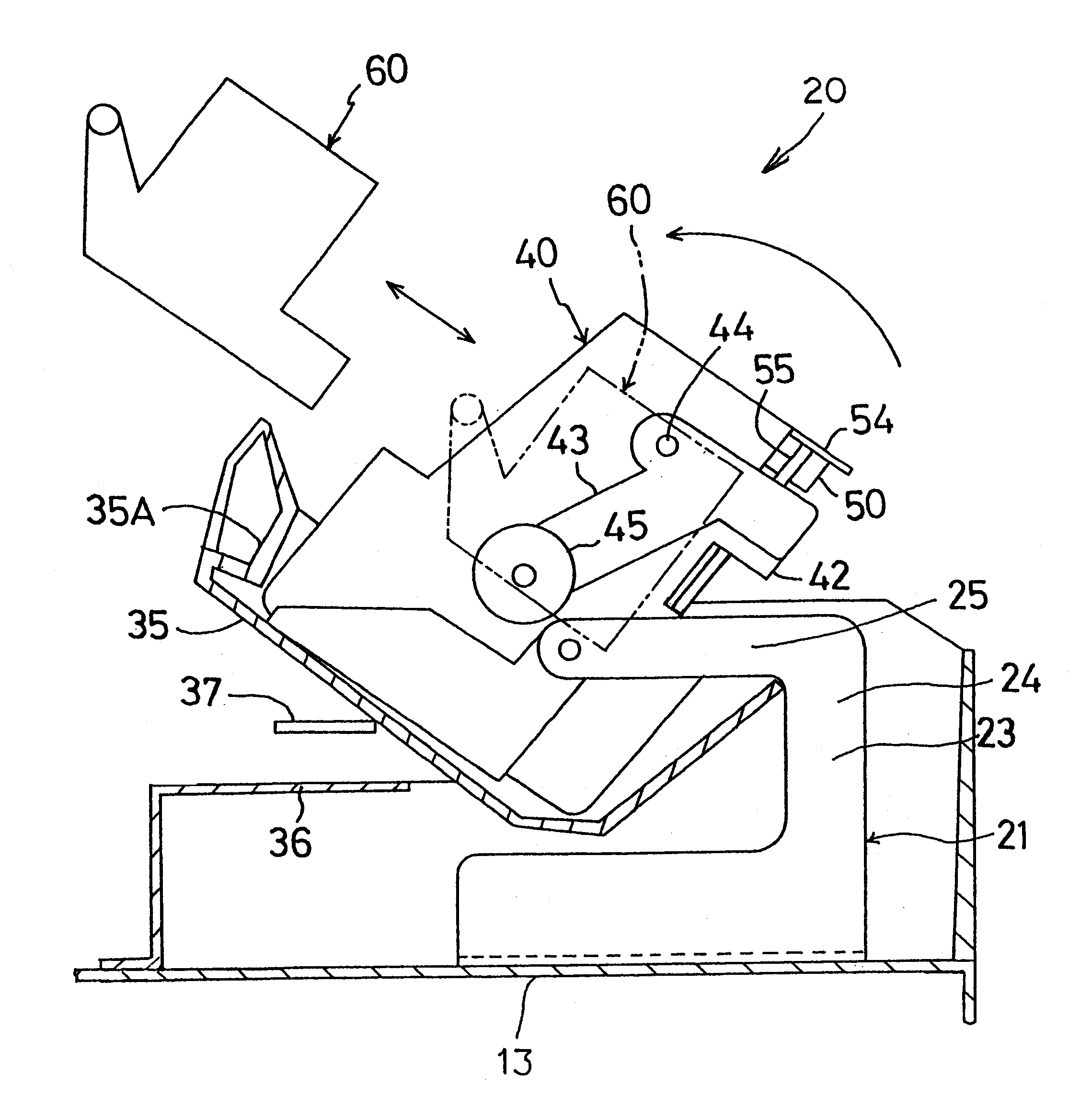
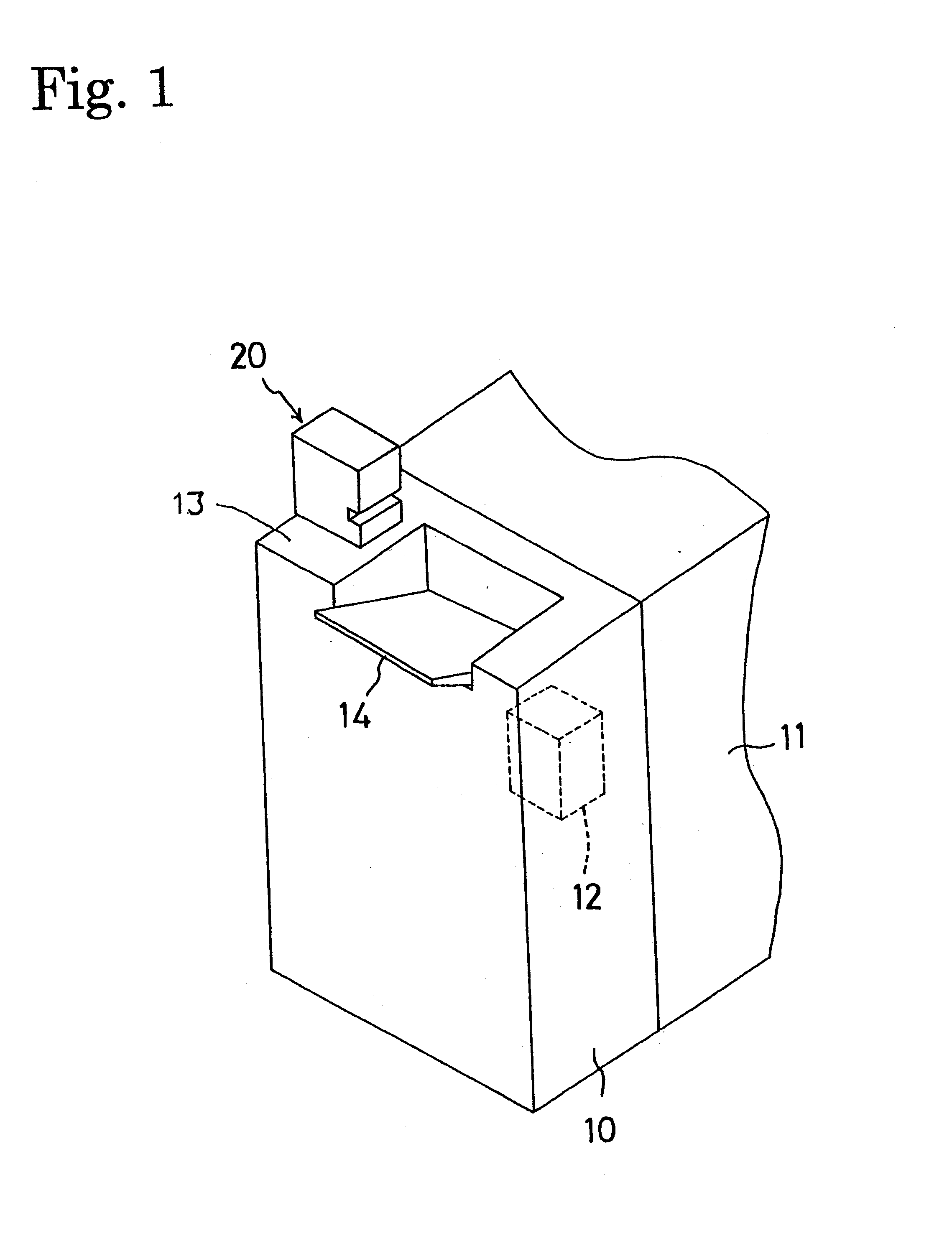
In FIG. 1 reference numeral 10 denotes a post processing apparatus disposed to a body of copying machine 11. In the post processing apparatus 10, an upside down type stapler 12 is disposed for binding a pile of printed sheet which is discharged from the copying machine body 11 with the surface of copied side down. On the top surface of post processing apparatus 10, another upside down type stapler 20 is also provided. A stapler body 40 of the stapler 20 (Refer to FIG. 2 to FIG. 4) has quite the same structure to that of the stapler body of stapler 12 (not shown) because the same kind of stapler is employed.

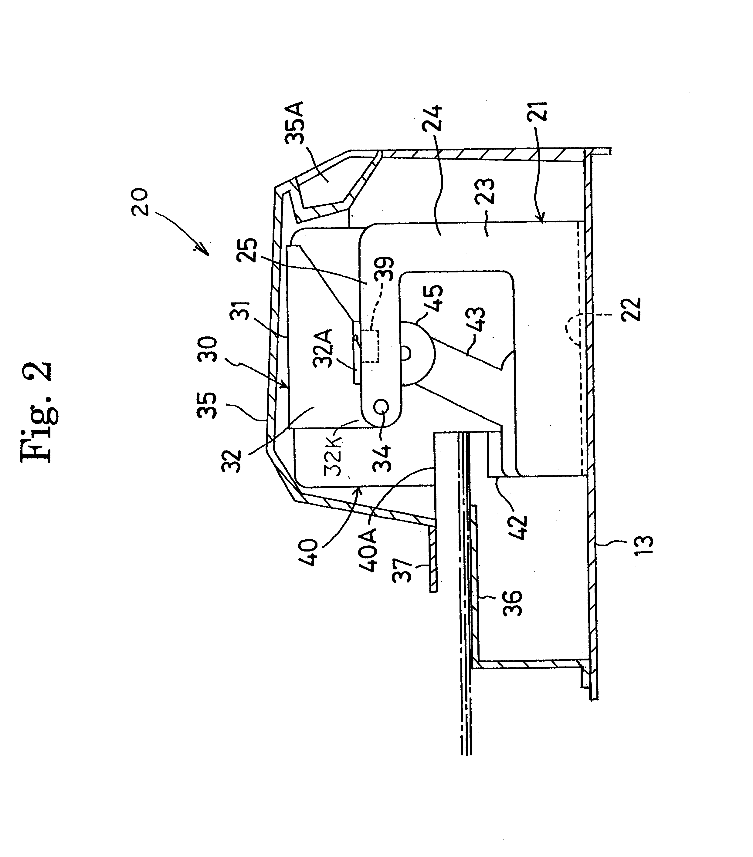
As shown in FIG. 2 to FIG. 4, the stapler 20 comprises a base plate 21 which is fixed on a top board 13 of the post process apparatus 10, a bracket 30 which is rotatably attached on the base plate 21, a stapler body 40 which is fixed on the bracket 30 and a ca...


PUM

PropertyMeasurementUnit
U-shapeaaaaaaaaaa
structureaaaaaaaaaa
rotational movementaaaaaaaaaa

Abstract

A stapler made with an upside down structure and used in downside up position in which loading of the cartridge is easily attained, is provided. The stapler comprises a base plate 21 which is fixed on a top board 13, a bracket 30 which is rotatably attached to an arm board portion 25 of the base plate 21, a stapler body 40 which is attached to the bracket 30 and a stopper 70 which fixes the stapler body 40 in its downside up posture.

Description

1. Field of the InventionThe present invention relates to a stapler, for example, which is disposed out of online for post processing on copied paper such as a post processing apparatus of the copying machine.2. Description of the Prior ArtHeretofore there is well known a stapler which is disposed to a copying machine and so on, as shown in FIG. 8.The stapler of this kind comprises a cartridge K in which a plurality of staples sheets S in multi-layered form is contained, a sending mechanism E by which the sheet of staples S is sent to a driving out portion U, a driver D) which drives out the staple from the driving out portion U by reciprocal movement thereof and a table Z which has a clincher (not shown) to clinch the front end portions of driven out staple. The table Z is arranged to be capable of upward or downward moving in order to put and hold a pile of sheets to be bundled when it locates at upper position. The reference character W is a forming plate to form a staple in U-sh...

Claims


Application Information

Patent Timeline
Patent Type & Authority Patents(United States)
IPC IPC(8): B27F7/38B27F7/19B27F7/00B27F7/21
CPCB27F7/38B27F7/19
Inventor ISHIZAKI, KUNIO
Owner MAX CO LTD
Learn More