
Rail vehicle having a driver's cab provided with an energy-absorbing structure adapted to cope with a collision above the frame of the vehicle

a technology for drivers and vehicles, applied in the direction of shock absorbers, roofs, elastic dampers, etc., can solve the problems of not being able to adapt to coping with impact and threatening the life of drivers, and achieve the effect of reducing these drawbacks and being simple and inexpensive to implemen

Inactive Publication Date: 2003-05-13
ALSTOM TRANSPORT TECH SAS
View PDF12 Cites 43 Cited by
  • Summary
  • Abstract
  • Description
  • Claims
  • Application Information

AI Technical Summary

Benefits of technology

An object of the present invention is to mitigate these drawbacks by providing a rail vehicle whose driver's cab is provided with a protective shield that is adapted to absorb the energy from an impact with an obstacle that hits the driver's cab above the level of the solebars of the vehicle frame, and that is simple and inexpensive to implement.

Problems solved by technology

However, such a structure is adapted to absorb energy from a major impact at the level of the solebars of the vehicle frame, but it is not adapted to coping with an impact with an obstacle that hits the driver's cab of the rail vehicle above the level of the frame.
Such an impact can occur when an obstacle hits the rail vehicle directly level with the driver's cab, and it can also occur when the impact is with an obstacle for which the energy-absorbing elements of the frame are overdimensioned and cannot therefore absorb the impact properly.
In such a case, the high rigidity of the frame and the downward-sloping shape of the end of the train usually cause the obstacle that is hit to be lifted up so that it then strikes the driver's cab and causes uncontrolled deformation thereof, thereby threatening the life of the driver.

Method used


Image

  • Rail vehicle having a driver's cab provided with an energy-absorbing structure adapted to cope with a collision above the frame of the vehicle
  • Rail vehicle having a driver's cab provided with an energy-absorbing structure adapted to cope with a collision above the frame of the vehicle
  • Rail vehicle having a driver's cab provided with an energy-absorbing structure adapted to cope with a collision above the frame of the vehicle

Examples


Embodiment Construction

To make the drawings clearer, only those elements which are necessary to understanding the invention are shown. Like elements have like references from one figure to another.

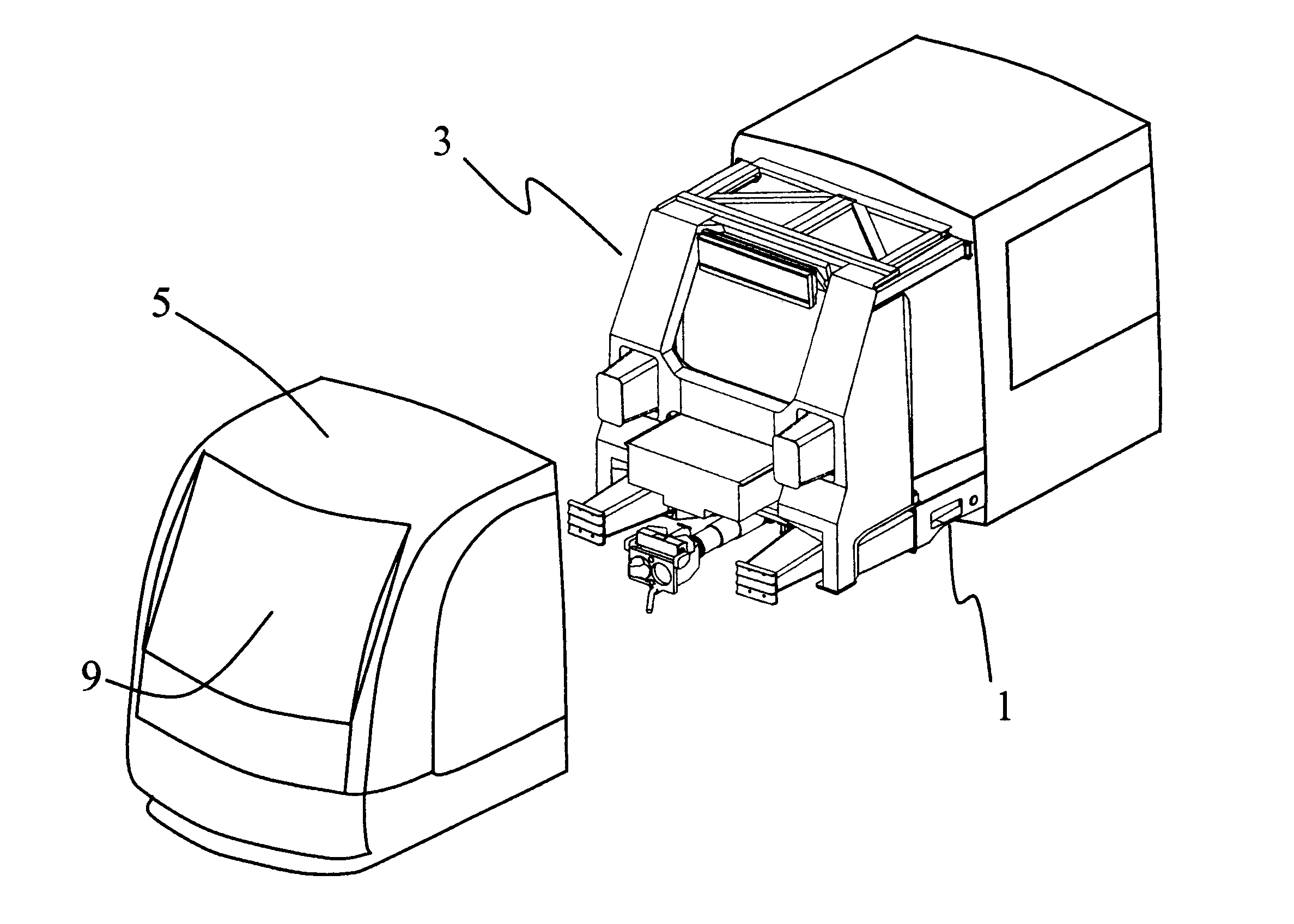
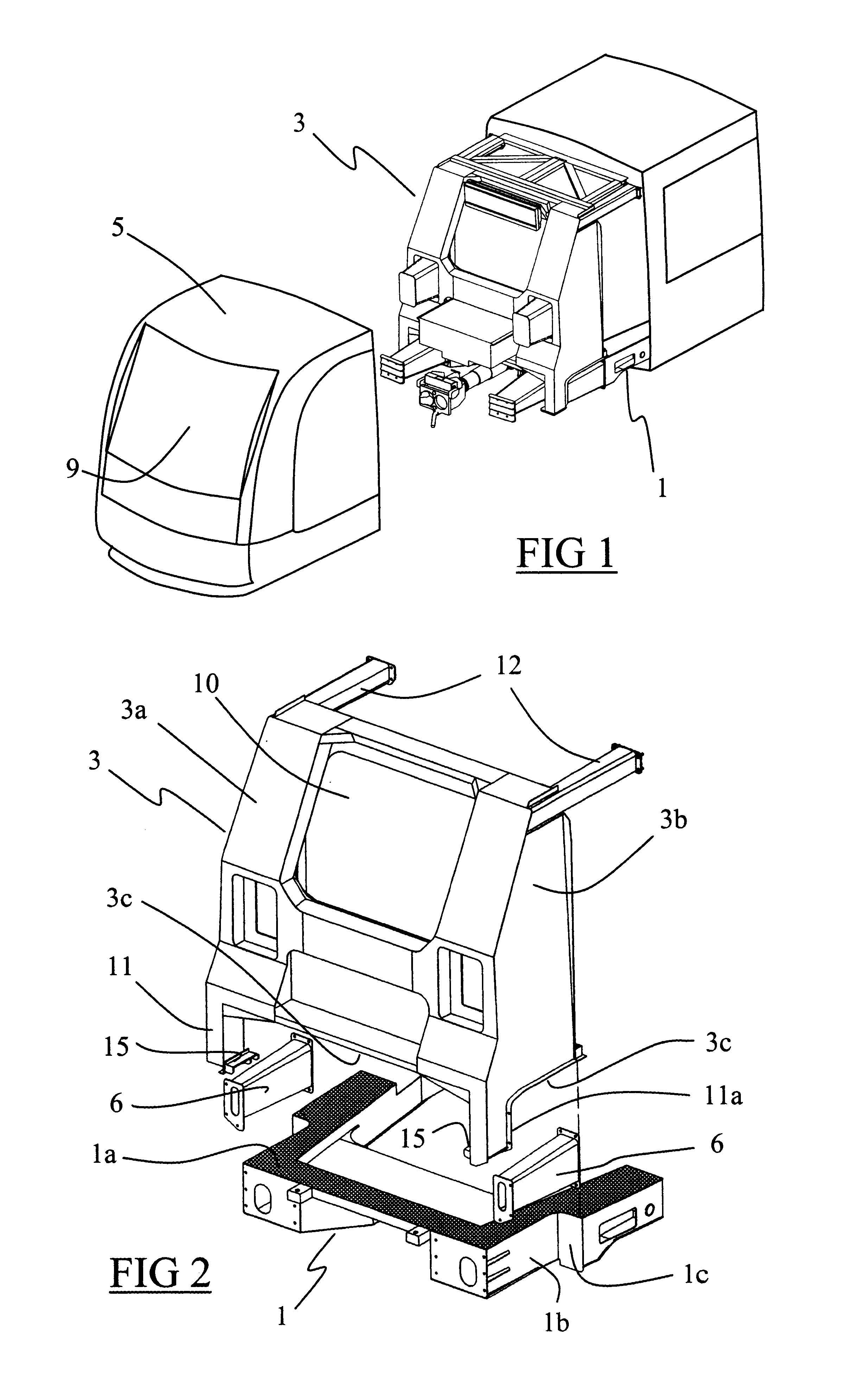
FIG. 1 shows the front end of a rail vehicle having a non-deformable rigid frame 1 providing rigidity for the vehicle, and a skin 5 forming an aesthetically-pleasing casing for the vehicle and supporting a windscreen 9.

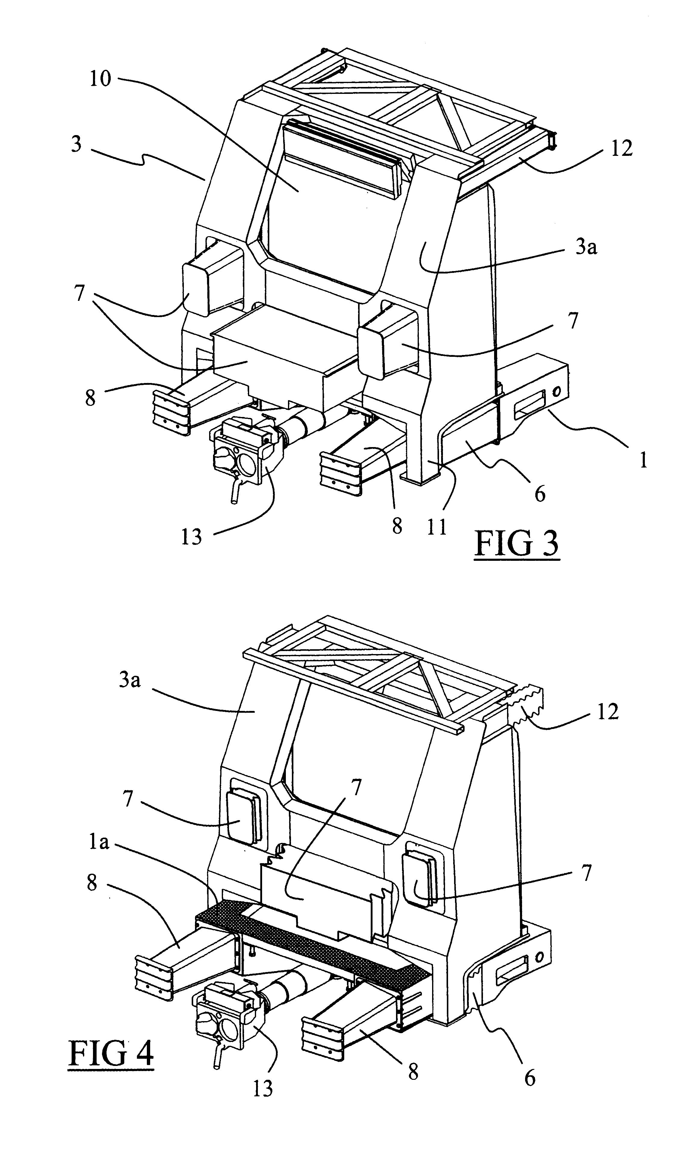
The vehicle is equipped with a driver's cab provided with a structure for protecting the driver. The structure is shown in exploded manner in FIG. 2 and is interposed between the inside of the driver's cab and the portion of the skin 5 that defines the front face of the vehicle. This structure has a rigid protective shield 3 that is non-deformable, that has a front wall extending vertically over substantially the entire height of the driver's cab, and that has two side walls 3b extending on either side of the driver's cab. The front wall 3a is provided with a wide opening 10 facing the windscreen ...


PUM


Abstract

A rail vehicle having an end provided with a driver's cab, said vehicle having a rigid frame extending under said driver's cab, said rail vehicle having a protective shield disposed in front of said driver's cab and provided with a rigid structure, said protective shield resting on said frame and being connected to said frame via at least one energy-absorbing element interposed locally between the shield and the frame.

Description

The invention relates to the field of construction of vehicles, in particular rail vehicles having driver's cabs, and it relates to such a vehicle that has an energy-absorbing structure for protecting the driver of the vehicle in the event of collision.Current rail vehicles are equipped at their ends with means serving to withstand stresses to which the vehicle is subjected under normal running conditions and when "docking" impacts occur at low speeds.It is also known, from Document FR-A-2 698 840, that it is possible to equip rail vehicles having driver's cabs with energy-absorbing metal structures for the purpose of protecting the passengers and the driver of the vehicle in the event it is subjected to major impacts, e.g. when it collides with another train. The vehicle then has dynamic plastic deformation zones formed of fixed or interchangeable energy-absorbing elements that are provided at the ends of the vehicle.However, such a structure is adapted to absorb energy from a majo...

Claims


Application Information

Patent Timeline
Patent Type & Authority Patents(United States)
IPC IPC(8): B61D17/04B61D17/06B61C17/00B61D15/00B61D15/06B61C17/04B61D17/00B61F19/04
CPCB61C17/04B61D17/06B61D15/06
Inventor GODIN, MARCELGIELCZINSKI, GERARDLANGLET, JEAN-MARCBONEILL, CHRISTIANGUILLOTEAU, ISABELLE
Owner ALSTOM TRANSPORT TECH SAS
Learn More