Passenger detecting system and air bag apparatus using the same
a technology of passenger detecting system and air bag, which is applied in the direction of using reradiation, pedestrian/occupant safety arrangement, instruments, etc., can solve the problems of complex processing, lack of accuracy, and high cos
- Summary
- Abstract
- Description
- Claims
- Application Information
AI Technical Summary
Problems solved by technology
Method used
Image
Examples
first embodiment
Also, in the interface circuit, the impedance converting circuit 23 is composed of an operational amplifier 23a having an amplification factor of 1. Therefore, the output side of the impedance converting circuit 23 is set to the low impedance, so that the current necessary for the CPU of the control circuit 20 to read can be taken out without any influence to the input side. The AC-DC converting circuit 24 is connected with the output of the impedance converting circuit 23. The AC-DC converting circuit 24 is composed of a smoothing circuit which is composed of a resistor 24a and a capacitor 24b. The output of the AC-DC converting circuit 24 is supplied to the control circuit 20 as the signal data, as in the
second embodiment
Next, the operation of this passenger detecting system in the second embodiment will be described with reference to FIGS. 14 and 20 and FIGS. 21A to 21D.
First, only the switch 18a of the switching circuit 18 is closed in response to the switching control signal from the control circuit 20, and the other switches 18b to 18f are opened. By this, the gate signal is transmitted to the switch 11b of the oscillating circuit 11A in the interface circuit Aa, as shown in FIG. 21A. Each time the gate signal becomes high, the switch 11b is turned on, so that the drain is set to the ground level is not outputted and the high frequency low voltage signal to the antenna electrode 4a. It should be noted
that in this case, the electric charge which has accumulated in a capacitance component around the antenna electrode 4a is discharged through the switch 11b.
On the other hand, when the gate signal becomes low, the switch 11b is turned off. Therefore, a high frequency low voltage signal with the appr...
third embodiment
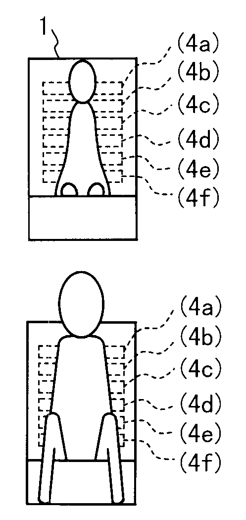
In this manner the third embodiment, the current determined in accordance with the capacitance component around the antenna electrode flows through the antenna electrodes 4a to 4d in accordance with the high frequency low voltage signal from the oscillating circuit 11. In this case, the voltage drop associated with the current is caused by the resistor 115 which is connected with the transmission system. The line voltage of the transmission system becomes the voltage which is associated with the current which flows through the antenna electrode. The current which flows through the antenna electrode is changed depending upon whether or not a passenger is present in the seat 1 and, when a passenger is present, whether or not the passenger is an adult. Therefore, by converting the line voltage from an alternating current into a direct current in the current detecting circuit 15, a direct current signal data is obtained to enable the passenger detection determination the signal data and...
PUM
 Abstract
Description
Claims
Application Information
 - Generate Ideas
- Intellectual Property
- Life Sciences
- Materials
- Tech Scout
- Unparalleled Data Quality
- Higher Quality Content
- 60% Fewer Hallucinations
Browse by: Latest US Patents, China's latest patents, Technical Efficacy Thesaurus, Application Domain, Technology Topic, Popular Technical Reports.
© 2025 PatSnap. All rights reserved.Legal|Privacy policy|Modern Slavery Act Transparency Statement|Sitemap|About US| Contact US: help@patsnap.com


