
Armrest for vehicle seat and method of forming the same

a technology for vehicle seats and armrests, applied in the field of armrests, can solve the problems of incomplete creation of foam padding therein, unpleasant touch to users, and affecting the aesthetics of armrests

Inactive Publication Date: 2003-02-04
TACHI S CO LTD
View PDF7 Cites 17 Cited by
  • Summary
  • Abstract
  • Description
  • Claims
  • Application Information

AI Technical Summary

Benefits of technology

Accordingly, the injection hole can be formed in such region of the three-dimensional trim cover assembly where the hole itself is invisible from the outside and kept away from contact with a user. Thus, any objectionable cured spot at the injection hole is concealed, which originates from a part of liquid foaming material that has been leaked through the hole and cured there during the foaming process. This effectively keeps aesthetic, the outer appearance of armrest, and insures to avoid any unpleasant hard touch of the spot to a user's arm and other body portion.
Accordingly, the tubular bearing is utilized as a guide through which the injection nozzle can be precisely introduced toward the injection hole. A worker can therefore conduct a stable positioning of the injection nozzle relative to the trim covert assembly, which assures to stabilize a flow of liquid foaming material via the nozzle and injection hole into the trim cover assembly, thereby creating a uniform resultant foam padding therein with its unchanged quality.

Problems solved by technology

Hitherto, the armrests thus formed have encountered such problem that an objectionable residual cured spot of the liquid foaming material remains at and around the injection hole in the trim cover assembly since a part of the liquid foaming material has been leaked outwardly through that hole during the foaming process and cured there into such objectionable spot.
This allows the objectionable cured spot to be viewed from the outside, impairing the outer aesthetic appearance of armrest, and also causes an unpleasant touch to a user whose arm contacts the wall part of armrest where the cured spot in question lies.
Such conventional steps have posed a difficulty in retaining an optimum position of the injection nozzle relative to the injection hole of trim cover assembly and caused the trouble that the liquid foaming material is not evenly filled in the trim over assembly, thus resulting in an incomplete creation of foam padding therein.

Method used


Image

  • Armrest for vehicle seat and method of forming the same
  • Armrest for vehicle seat and method of forming the same
  • Armrest for vehicle seat and method of forming the same

Examples


Embodiment Construction

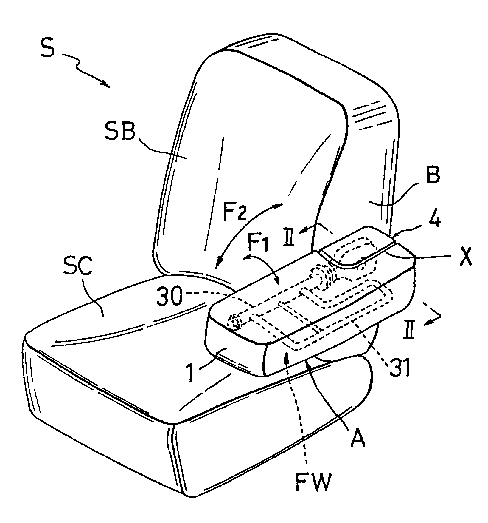
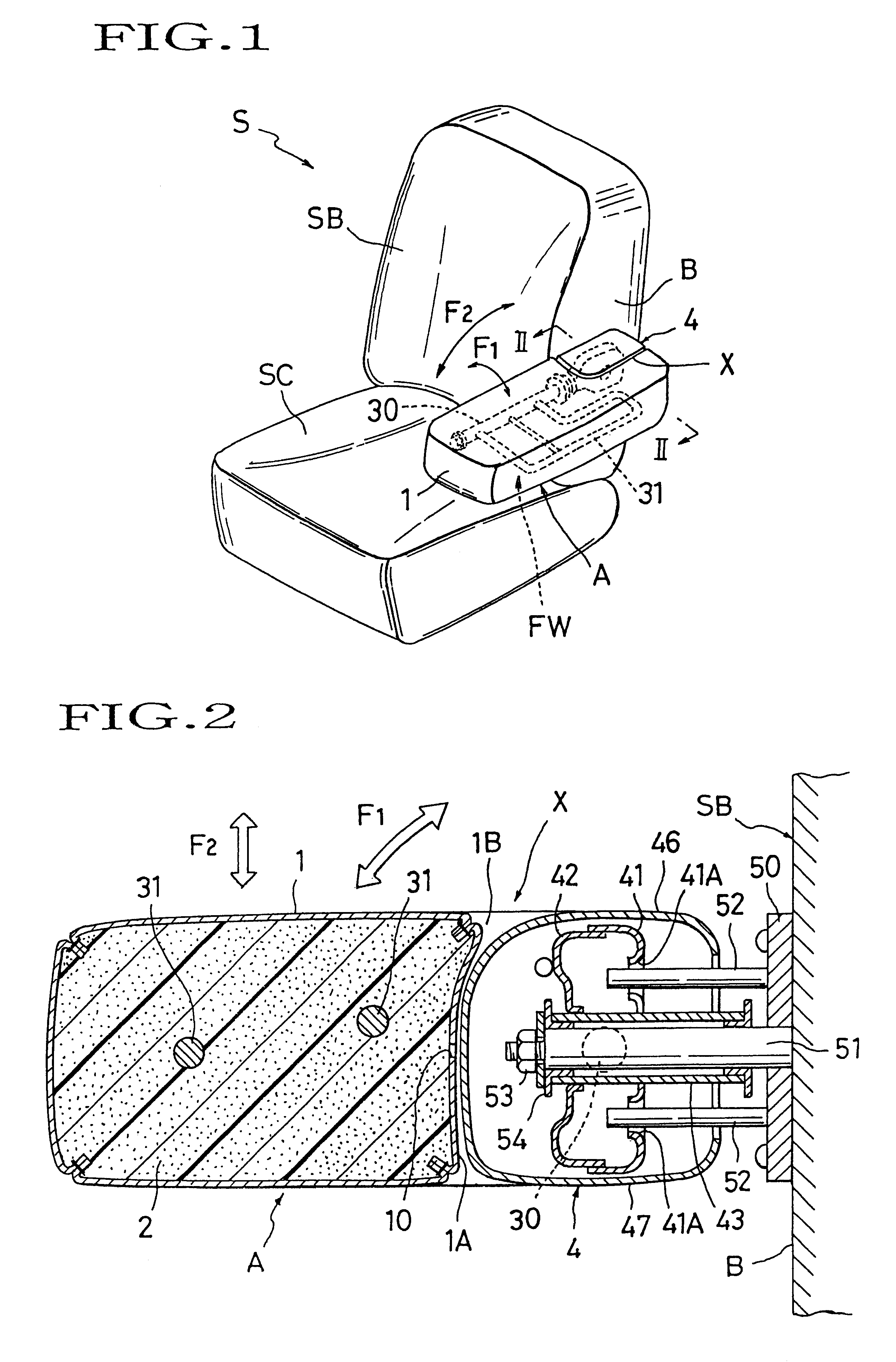
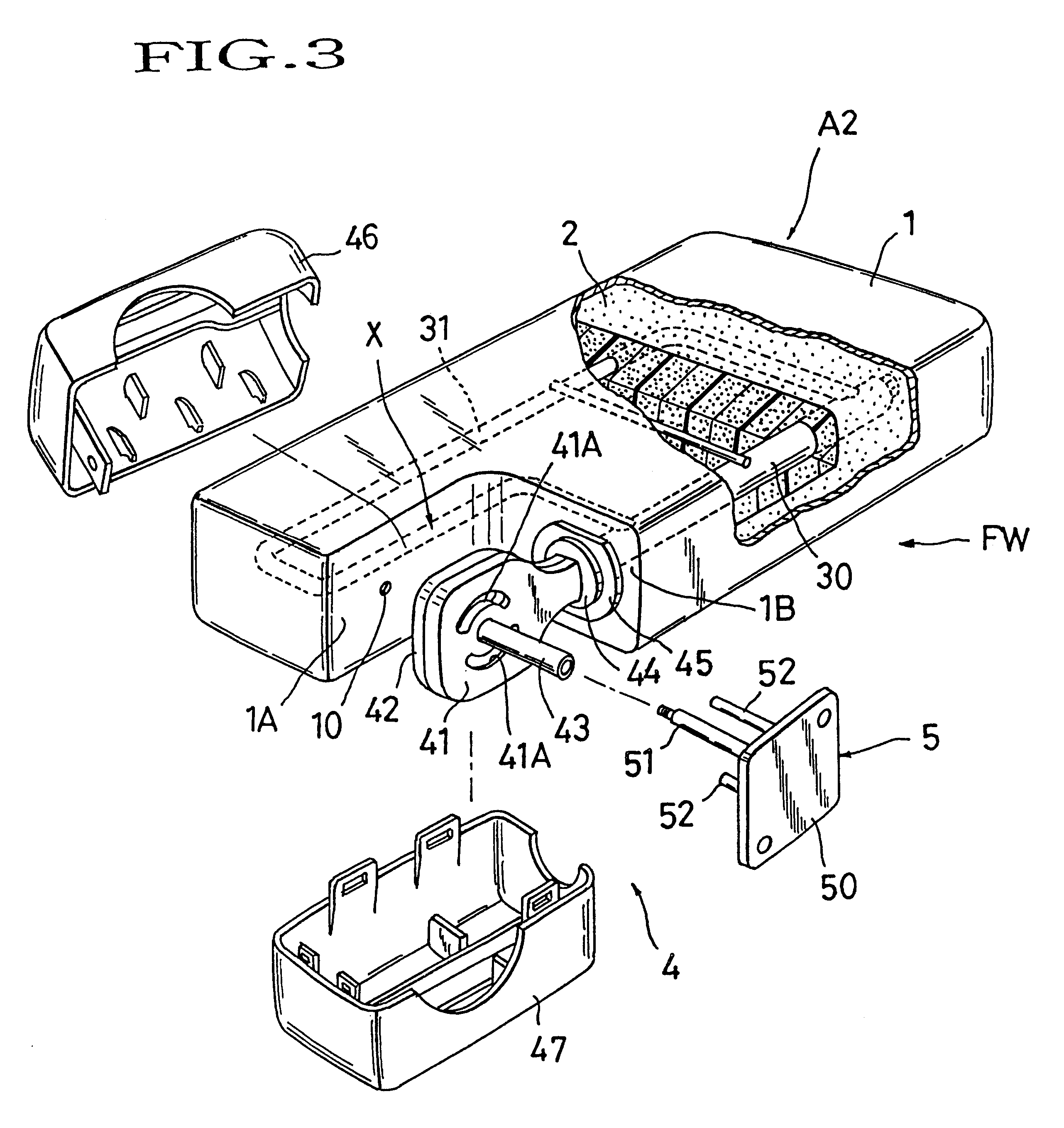
Referring to FIGS. 1 through 7, there are illustrated an armrest for vehicle seat and a method for forming the same in accordance with the present invention. The armrest, generally designated by (A), is of the type including a connecting portion (4) and an armrest body having a recessed region (X) so configured to partly surround the outer sides of such connecting portion (4). Designaton (S) denotes an ordinary vehicle seat which has a seat cushion (SC) and a seat back (SB). As shown, the armrest (A) is attached rotatably via the connecting portion (4) to one lateral wall (B) of the seat back (SB).

As understandable from FIGS. 1 and 2, the shown armrest (A) is of such a type that enables a user to rotate the body of armrest in both vertical direction (F2) and lateral (rightward and leftward) directions (F1) with respect tol the connecting portion (4) or the seat (S). For, in brief, the framework (at FW) of armrest (A) includes a first axis of rotation at (43) (51) for allowing vertic...


PUM


Abstract

An armrest for vehicle seat is provided, whose armrest body has a region so configured as to surround a connecting portion by which the armrest is rotatably connected with a seat back of the seat, wherein a cubic trim cover assembly of the armrest is formed with a local side defined on and along such region of armrest body. Formed in such local side of trim cover assembly is an injection hole for allowing injection of a liquid foaming material into the inside of trim cover assembly, so that the injection hole itself is not exposed outwardly of the armrest body, thus keeping the user away from contact with an objectionable spot originating from a part of liquid foaming material that has been leaked through the injection hole and cured there during a foaming process. The connecting portion may include a tubular bearing, and the injection hole may be formed at any point in that particular local side for coaxial alignment with the tubular bearing, during the foaming process, so that an injection nozzle may be introduced through the tubular bearing precisely into the injection hole.

Description

BACKGROUND OF INVENTION1. Field of the inventionThe present invention relates to an armrest for use on a vehicle seat and a method for forming the same. In particular, the invention is directed to a foamed armrest having a foam padding in its trim cover assembly, and also directed to a method for forming such kind of armrest under the steps of injecting and curing a liquid foaming blase material in a three-dimensional trim cover assembly preformed by sewing in a predetermined shape of armrest.2. Description of Prior ArtIn general, an armrest for use with a vehicle seat is mounted on a support shaft projected outwardly from a lateral side of seat back and rotatable about the shaft in a vertical direction. The armrest, therefore, may be selectively located in one of a horizontal use position and an upright non-use position, so that a passenger can rest his or her arm thereon at the horizontal use position, or can move the armrest to the upright non-use position set along the vertical ...

Claims


Application Information

Patent Timeline
IPC IPC(8): B60N2/46B60N2/70B60N2/75
CPCB60N2/4606B60N2/7017B60N2/4633B60N2/753B60N2/767
Inventor IKEDA, TETSUOKATO, TAKASHI
Owner TACHI S CO LTD
Learn More