
Machine for harvesting fruit and berries and the like from fruit trees and bushes planted in a row, and shaker rod for a machine of this kind

a technology for a shaker rod and a machine is applied in the field of shaker rod for a shaker rod and a machine for harvesting fruit and berries and the like from fruit trees and bushes planted in a row, which can solve the problems of increasing the oscillatory movement and the speed of the active part of the shaker rod, aggravate the damage caused to the vine, and it is difficult to prevent unwanted vertical movemen

Inactive Publication Date: 2003-01-07
NEW HOLLAND BRAUD
View PDF6 Cites 18 Cited by
  • Summary
  • Abstract
  • Description
  • Claims
  • Application Information

AI Technical Summary

Benefits of technology

The principal aim of the present invention is therefore to provide a harvesting machine of the type defined in the preamble whose shaker members in the form of flexible rods, are in use less subject to unwanted movement in the third direction.
A subsidiary object of the present invention is to provide a harvesting machine of the type defined above in which the shaker members also have an increased service life.
Under the above conditions, each rod is clearly more rigid in the vertical direction (third direction) than in the horizontal direction (second direction). Each rod is therefore less likely to be subject to unwanted vertical movement and if there is any such movement its amplitude is significantly reduced compared to that of a circular cross-section rod. Furthermore, by keeping the vertical dimension of the cross-section of said base part or that of each rod less than a predefined value, which is in turn at most equal to, and preferably less than, the diameter of prior art circular cross-section rods, each rod offers up to the vine or other fruit-bearing bush to be shaken a contact surface area the same as or smaller than that of prior art circular cross-section rods. This prevents the rod having an enlarged contact surface area, because of the oblong shape of the cross-section of said base part, which could burst the grapes or other berries on impact with the shaker rods. Moreover, the wear of each rod by abrasion can influence its horizontal stiffness, unless measures specified hereinafter are applied, but has virtually no effect on the vertical stiffness of the rod. Consequently, prolonged use of rods in accordance with the invention does not increase the risk of damage caused to the vines by unwanted vertical movements.

Problems solved by technology

However, while detaching bunches of grapes or individual grapes, the shaker members may damage the vine, which may be detrimental to the health of the vine and to the crop itself It is therefore generally necessary to find a compromise between the various parameters mentioned above in order to obtain an acceptable percentage of harvested grapes or bunches of grapes without giving rise to unacceptable damage to the vine.
In particular, for a given frequency of oscillation, the amplitude of the oscillatory movement and the speed of the active part of the rod are increased, especially in the case of rods with a free rear end, and this can aggravate the damage caused to the vine.
Although a compromise may be found between the various parameters mentioned above to obtain an acceptable percentage of grapes or bunches of grapes or other berries harvested without causing excessive damage to the vine or other fruit-bearing bushes carrying the berries to be harvested, with shaker members consisting of circular cross-section rods it is difficult to prevent unwanted vertical movement of the rods in use, i.e. in a third direction perpendicular to the first and second directions mentioned above, in addition to their horizontal (second direction) oscillatory movement, which is the only one which is beneficial in terms of shaking the fruit-bearing bushes and thus of harvesting the fruit.
The disadvantage of these unwanted vertical movements is that they detach leaves which are mixed with the harvested fruit and therefore complicate cleaning of the crop.
Also, the side of the shaker rods in contact with the vegetation of the fruit-bearing bushes to be shaken is worn by abrasion in use.
As a result the flexibility of each rod in a horizontal oscillation plane, i.e. in the plane defined by the first and second directions mentioned above, increases as the rod wears away, making shaking less effective.
This is because, as the rod becomes more flexible, it becomes less capable of entraining with it, during its oscillatory motion, the vegetation of the fruit-bearing bush to be shaken.

Method used


Image

  • Machine for harvesting fruit and berries and the like from fruit trees and bushes planted in a row, and shaker rod for a machine of this kind
  • Machine for harvesting fruit and berries and the like from fruit trees and bushes planted in a row, and shaker rod for a machine of this kind
  • Machine for harvesting fruit and berries and the like from fruit trees and bushes planted in a row, and shaker rod for a machine of this kind

Examples


example 1

A rod 11 was made from a single material, namely PA 6.6 polyamide (E=3300 N / mm.sup.2), and had a circular cross-section (FIG. 6) with a diameter of 30 mm and a length of 1.79 m. A wear u of 6 mm was to be tolerated (FIG. 14). Under these conditions, the rod had the following characteristics:

When new:

I.sub.y =I.sub.x =39 761 mm.sup.4

R.sub.x =R.sub.y =3E. I.sub.y / L.sup.3 =0.0856 N / mm

When worn:

I.sub.y =24 440 mm.sup.4

R.sub.x =0.0522 N / mm

When worn, the horizontal stiffness was therefore no more than around 61% of the stiffness when new.

example 2

A rod the same length as in example 1 was made as shown in FIG. 11. The is coating 32 had a diameter c of 27 mm and the core 11a had a major axis a 19 mm long and a minor axis b 13 mm long. The core 11a was made of glass fibers and polyester resin (E.sub.1 =40 000 N / mm.sup.2) and the coating 32 was made of PA 6.6 polyamide (E.sub.2 =3300 N / mm.sup.2). Again, a wear u of 6 mm was to be tolerated (FIG. 15). The moment of area I.sub.1y of the core 11a, which is given by equation (2) above, was the same when the rod was new and worn:

I.sub.1y =2 049 mm.sup.4

The horizontal stiffness R.sub.1x and the vertical stiffness R.sub.1y of the core 11a, which are given by equations (5) and (6) above, were the same when the rod was new and worn:

R.sub.1x =0.0429 N / mm and R.sub.1y =0.0916 N / mm

The moments of area I.sub.2x and I.sub.2y of the coating 32 when new are given by the equations:

I.sub.2x =.pi.(c.sup.4 -a.sup.3 b) / 64 (7)

I.sub.2y =.pi.(c.sup.4 -ab.sup.3) / 64 (8)

whence, in this case: I.sub.2x =21 7...

example 3

A rod the same length as in examples 1 and 2 had a shape similar to that of FIG. 11 but with the following dimensions:

a=18 mm; b=11 mm and c=25 mm.

The core 11a was made of carbon fiber and epoxy resin (E.sub.1 =130 000 N / mm.sup.2) and the coating 32 was made of polyurethane (E.sub.2 =60 N / mm.sup.2).

Under these conditions, the rod had the following characteristics: When new:

Here, when new, the horizontal stiffness R.sub.2x of the coating 32 represented only a negligible percentage (0.7%) of the global horizontal stiffness R.sub.x of the rod and the global vertical stiffness R.sub.y was twice R.sub.x.

When worn (u=6 mm).

In example 3, the global horizontal stiffness with 6 mm of wear represented 99.7% of the global horizontal stiffness when new. It can therefore be seen that, in this example, the wear had virtually no effect on the behavior of the shaker. Also, the global vertical stiffness R.sub.y was unchanged compared to the value when new and therefore remained twice R.sub.x. Also, ...


PUM


Abstract

In this harvesting machine using shaker members in the form of rods to shake the fruit-bearing bushes and harvest the fruit, each shaker rod has an elongate base part which has, in use, a required flexibility characteristic for the rod in a horizontal plane and which has an oblong cross-section whose height is greater than its width, said cross-section having two main geometrical axes which are respectively horizontal and vertical and dimensions of height and width such that its moment of area about the horizontal main axis is significantly greater than its moment of area about the vertical main axis and its height is less than a predefined value. The base part forms a core for the rod, which can further include a wear part which covers the core and which is made of a material and has a thickness such that the rod has flexibility characteristics in the horizontal and vertical planes that are practically unchanged relative to those of the core, even after substantial wear of the wear part.

Description

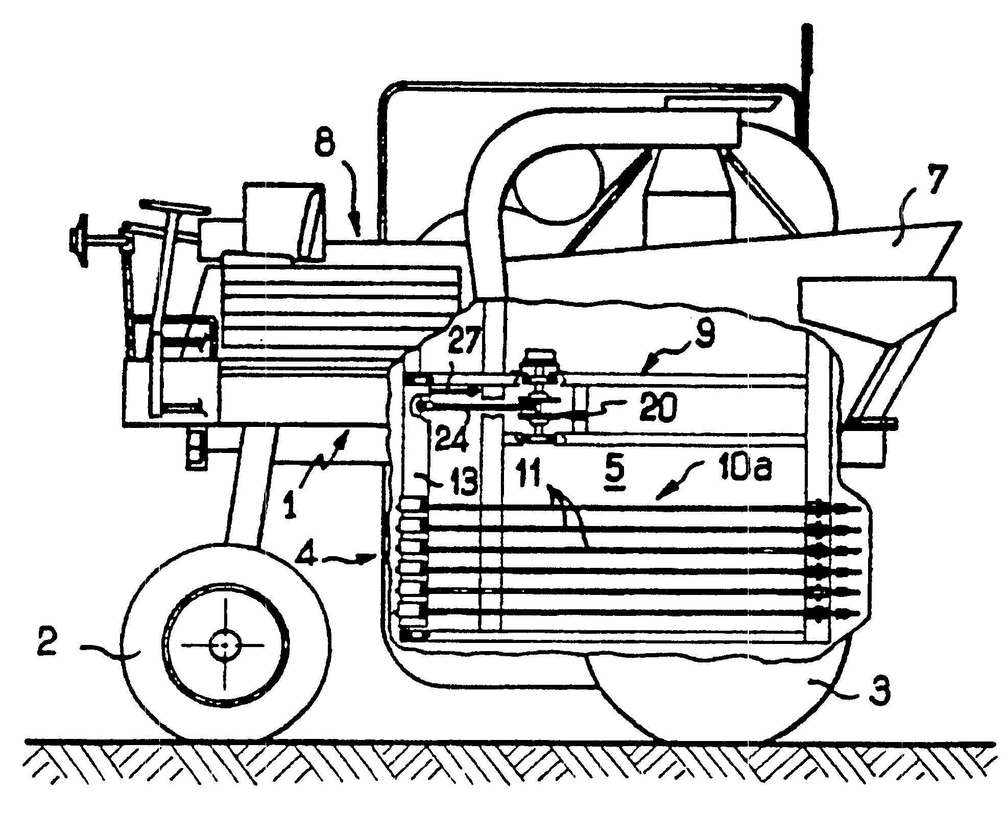
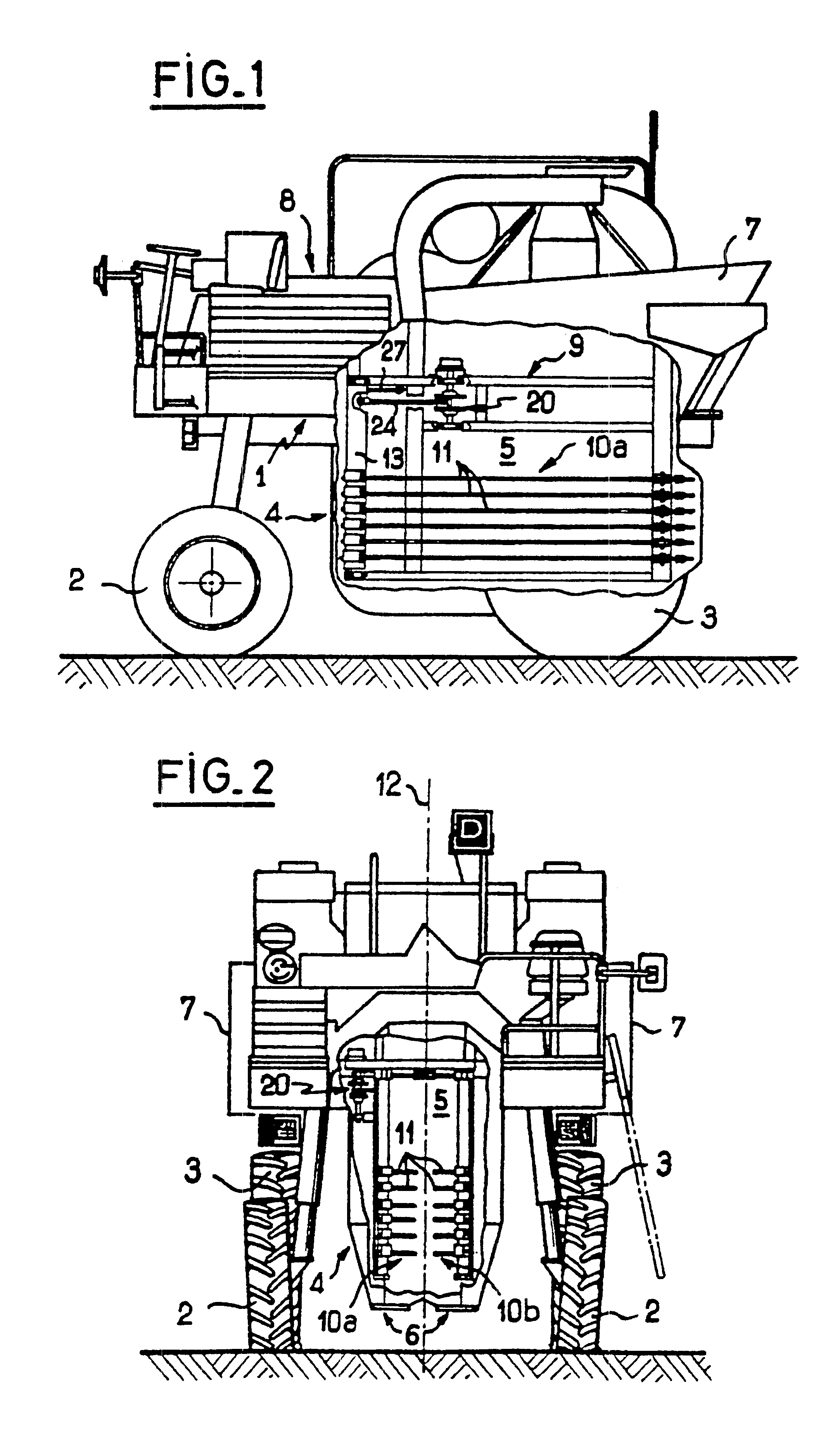
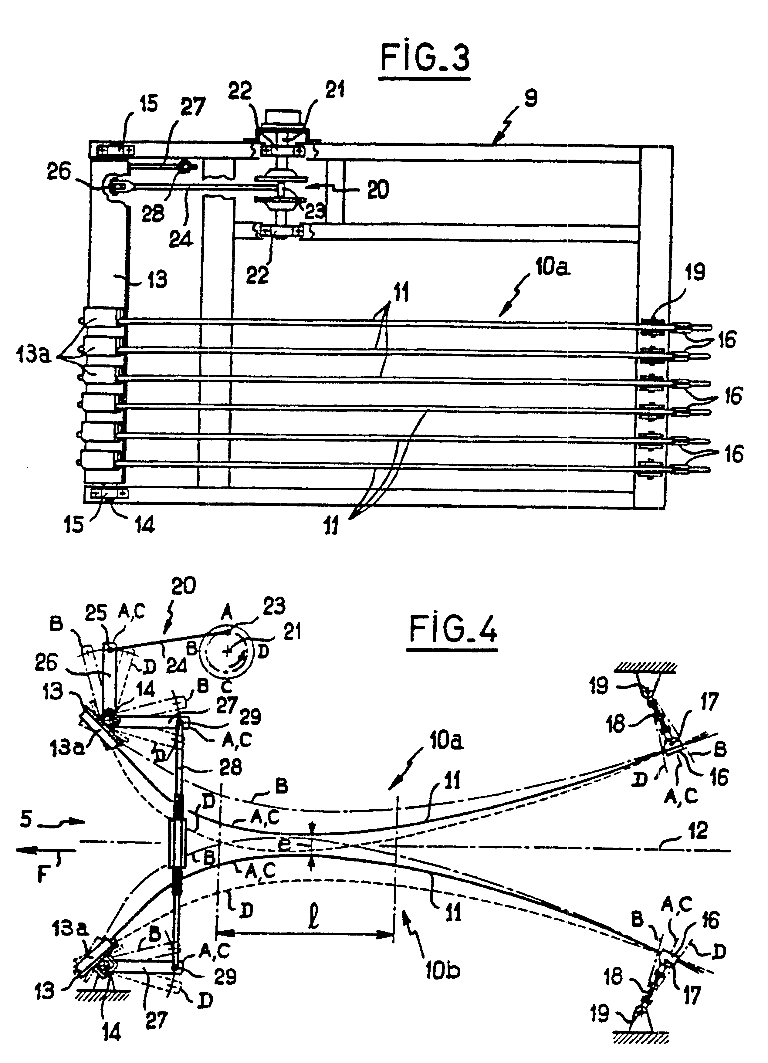
The present invention relates to a machine for harvesting fruits, berries and the like, from fruit trees and bushes planted in rows, of the type including a straddling chassis or frame capable of moving across a field, a shaker assembly mounted on the chassis and including at least one pair of elongate shaker members which have active parts extending in a first direction, broadly speaking in the longitudinal direction of the machine, and which are spaced transversely from each other and situated on respective opposite sides of the longitudinal median axis of the machine, each shaker member consisting of a flexible material rod, and a drive mechanism connected to the rods to drive them synchronously with a reciprocating motion in a second direction perpendicular to the first direction and defining therewith an oscillation plane for each rod.The invention relates in particular, although not exclusively, to harvesting grapes and it will be more particularly described in connection with...

Claims


Application Information

Patent Timeline
IPC IPC(8): A01D46/00A01D46/28
CPCA01D46/28
Inventor MERANT, JEAN-CAMILLELE NEVE, DANIEL H. A. M.
Owner NEW HOLLAND BRAUD
Learn More