
Thermal compensated compact bragg grating filter

Inactive Publication Date: 2002-12-10
II VI DELAWARE INC
View PDF8 Cites 31 Cited by
  • Summary
  • Abstract
  • Description
  • Claims
  • Application Information

AI Technical Summary

Problems solved by technology

One problem associated with prior-art fiber Bragg grating filters is their sensitivity to environmental temperature fluctuations.
However, they all have one or more certain drawbacks, including long lengths or other dimensions.
Further, the prior-art thermal compensated Bragg grating filters are relatively complex and expensive to manufacture.
Furthermore, prior art devices that apply axial tension to the optical fiber tend to have a high failure rate due to the fact that over time the applied tension will cause failures in the optical fiber or the means used to attached the optical fiber.

Method used


Image

  • Thermal compensated compact bragg grating filter
  • Thermal compensated compact bragg grating filter
  • Thermal compensated compact bragg grating filter

Examples


Embodiment Construction

Persons of ordinary skill in the art will realize that the following description of the present invention is illustrative only and not in any way limiting. Other embodiments of the invention will readily suggest themselves to such skilled persons having the benefit of this disclosure.

Referring first to FIG. 3, a first prior-art thermal-compensated Bragg grating filter 10 is shown. An optical fiber 12 incorporating a grating region 14 as is known in the art is mounted between a first compensating member 16, formed from a material such as Invar or quartz, and a second compensating member 18 formed from a material such as aluminum or steel having a thermal expansion coefficient different from that of the first compensating member. The first compensating member 16 includes a central recess 20 and the compensating member 18 includes a central projection 22 partially extending into the recess 20. The optical fiber 12 is connected at the respective ends of the Bragg grating region 14 to th...


PUM


Abstract

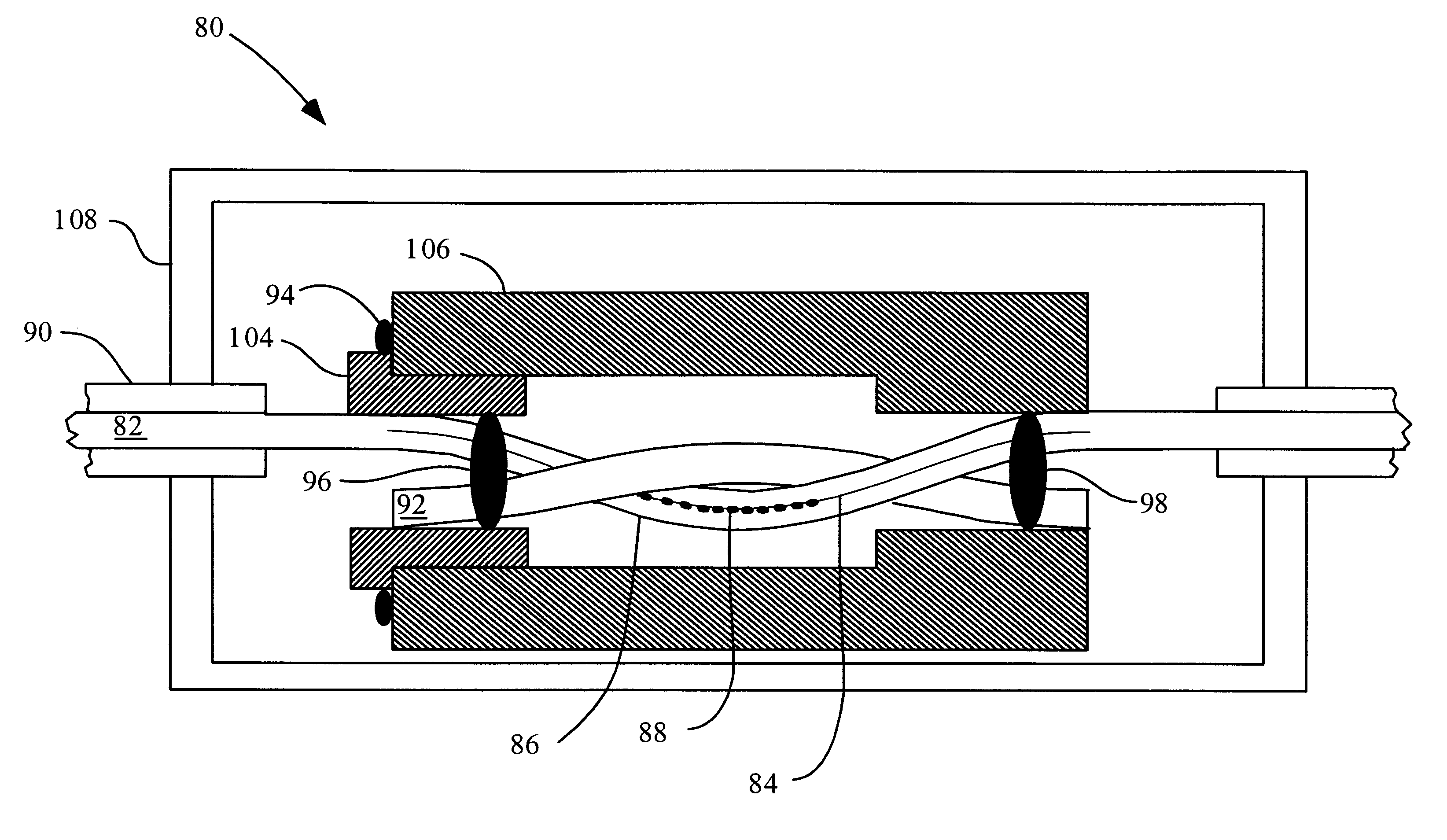
Various aspects of thermal compensated Bragg grating filters are disclosed. In one disclosed aspect, an optical fiber having a Bragg grating therein is laid adjacent to a torsion member, and the two are then rigidly affixed between a torsion adjusting member and a compensating member. The torsion adjusting member may then be rotated, twisting the optical fiber around the torsion member, and thus applying torsion to the optical fiber containing the Bragg grating, and changing the period of the Bragg grating. A further disclosed aspect provides an optical fiber, containing a Bragg grating filter therein, which is rigidly affixed between a torsion adjusting member and a compensating member in an axis other than the compensating member's longitudinal axis. The torsion adjusting member may then be rotated to apply torsion to the optical fiber, and change the period of the Bragg grating. Another disclosed aspect comprises an optical fiber, containing a Bragg grating filter therein, and a compensating member having a desired thermal coefficient of expansion. The optical fiber is bent through a curve and affixed to the compensating member such that torsion is applied to the Bragg grating region of the optical fiber.

Description

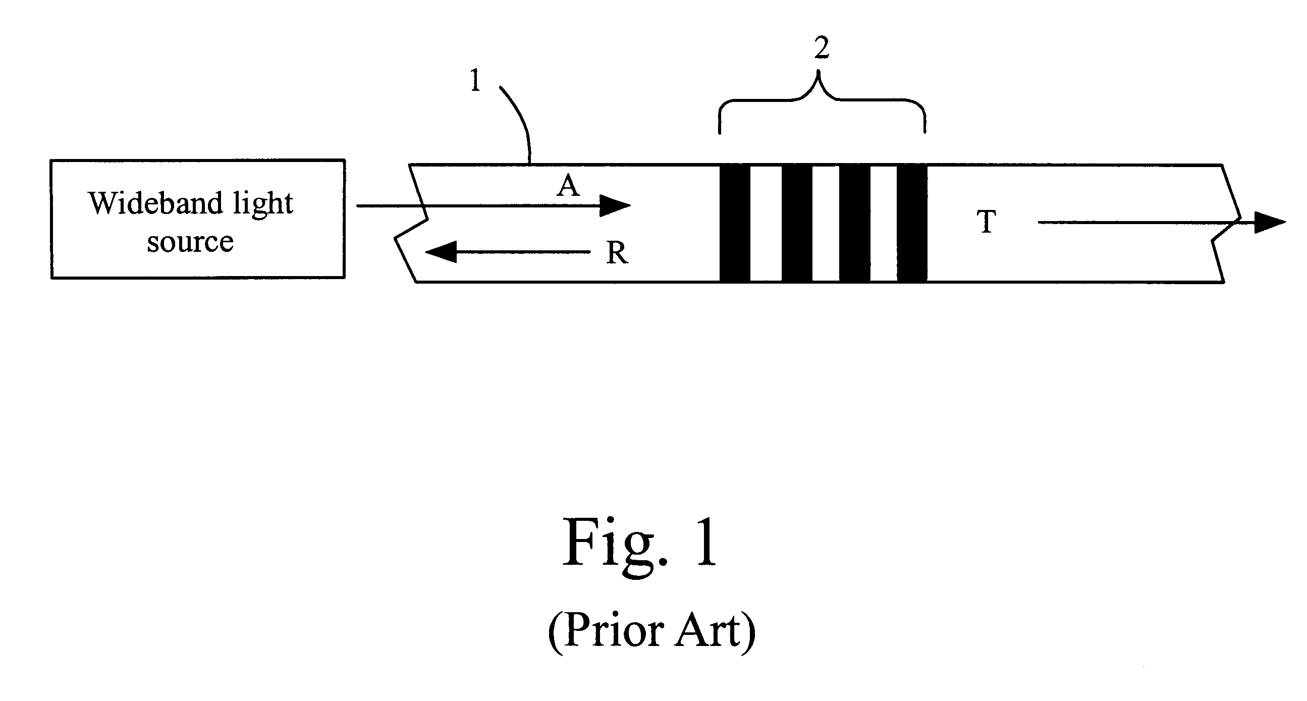
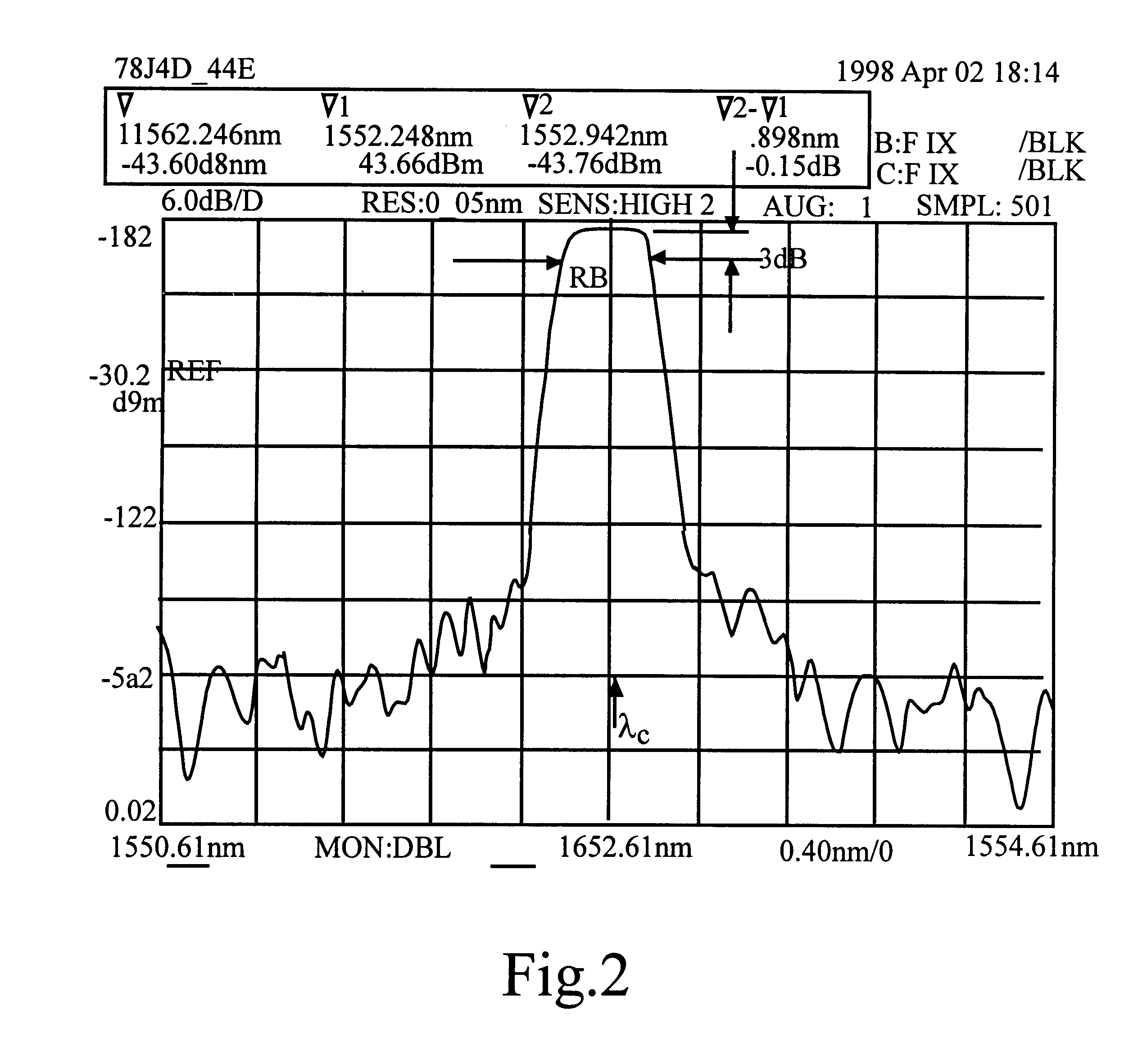
1. Field of the InventionThe present invention relates to optical fiber filters, and particularly to improved fiber Bragg grating filters.2. The Prior ArtFiber Bragg grating filters are known in the art. Fiber Bragg grating filters are becoming widely used because of the increased use of fiber optical systems. For example, fiber Bragg grating filters are used to filter out noise or unwanted wavelengths of light in optical distribution systems.FIG. 1 is a diagram showing the operation and measurement of a prior-art fiber Bragg grating filter. FIG. 1 shows an optical fiber 1 incorporating a Bragg grating portion 2. As is known by those of ordinary skill in the art, Bragg grating portion 2 is formed by applying energy such as laser energy to an optical fiber. The resulting deformations in the optical fiber increases the refractive index of the fiber periodically as shown in FIG. 1.The effects of fiber Bragg grating filters on applied light is demonstrated in FIG. 1 by applying the outp...

Claims


Application Information

Patent Timeline
IPC IPC(8): G02B6/34
CPCG02B6/0218G02B6/29398
Inventor CHEN, PETER
Owner II VI DELAWARE INC
Learn More