
Soundproof type engine driven work machine

a work machine and engine technology, applied in the direction of machines/engines, instruments, transportation and packaging, etc., can solve the problems of engine sound, reduced cooling air volume, and reduced cooling efficiency

Inactive Publication Date: 2002-12-10
DENYO LMTD
View PDF3 Cites 42 Cited by
  • Summary
  • Abstract
  • Description
  • Claims
  • Application Information

AI Technical Summary

Benefits of technology

The soundproof type engine driven work machine according to the present invention is composed as aforementioned. It is possible to improve the cooling efficiency extraordinarily as well as reducing the unfavorable noise. Further, it is possible to reduce the size of said soundproof casing.

Problems solved by technology

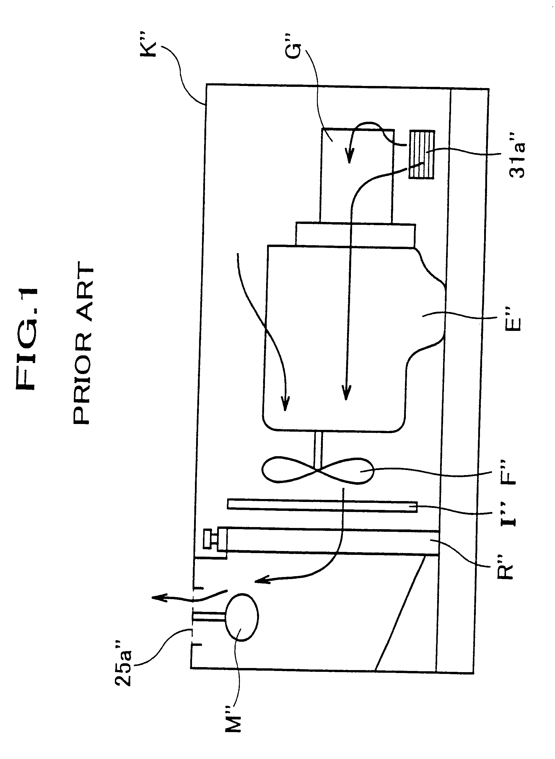
Thus, the cooling efficiency is much reduced.
This is a big problem of the engine sound.
However, against such construction, it is pointed out that the volume of the cooling air is reduced and cooling efficiency at each apparatus is reduced.
This will be in conflict with the concept that the size of the generator should be small.

Method used


Image

  • Soundproof type engine driven work machine
  • Soundproof type engine driven work machine
  • Soundproof type engine driven work machine

Examples


Embodiment Construction

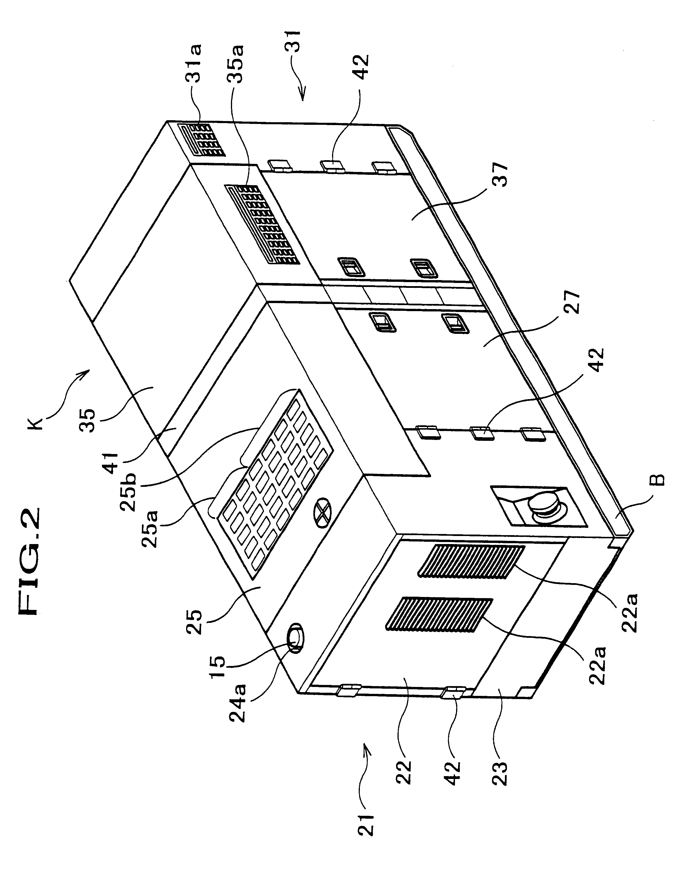
Now an example of the preferred embodiments of the soundproof type engine driven work machine according to the present invention is explained with reference to the accompanying drawings.

In the following explanation, the left and the right of a soundproof casing K correspond to the left and the right of the soundproof casing K when observed it from a rear frame 31 direction.

(1) Overall Construction of the Generator

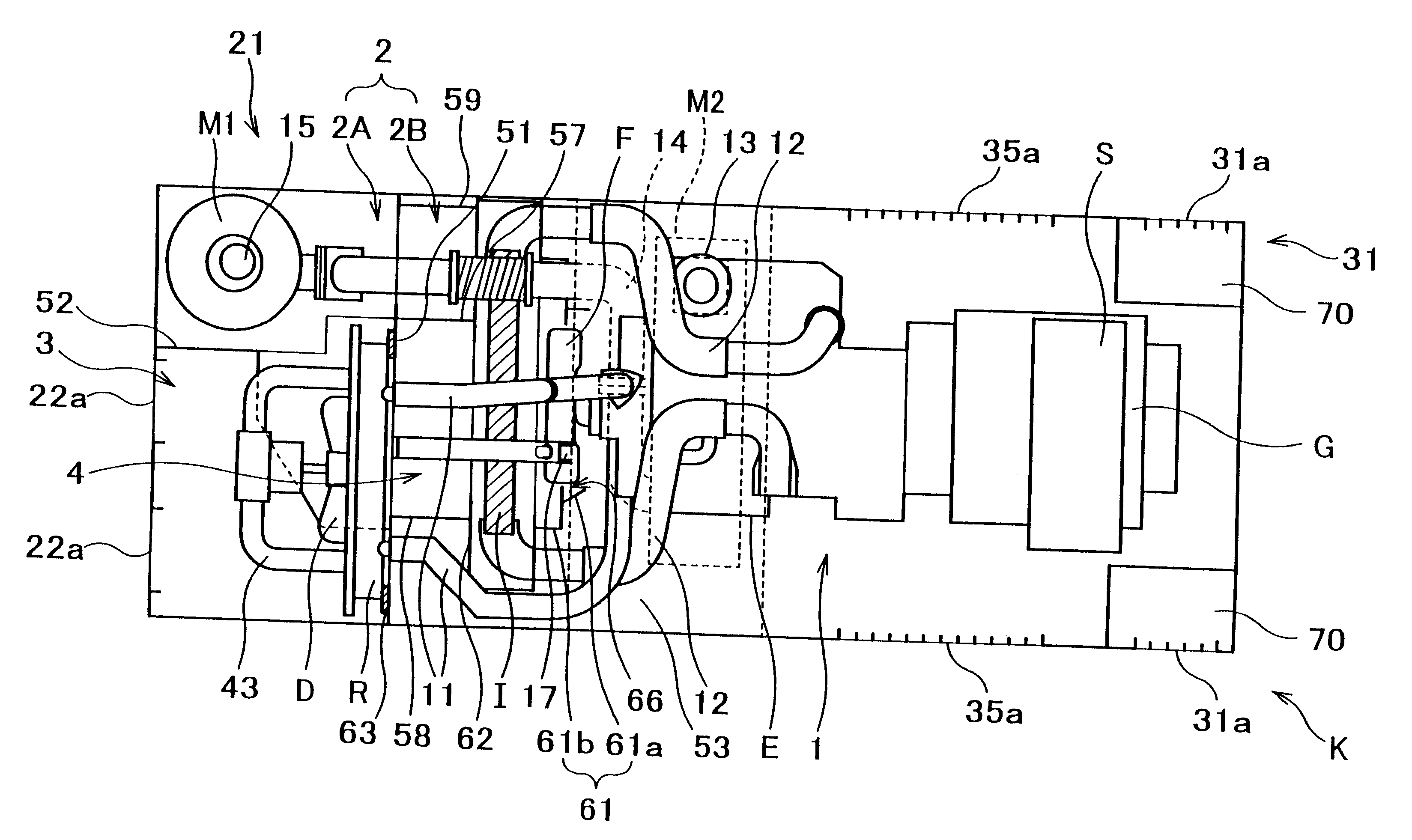
The generator according to the present invention, as shown in FIGS. 3, 4, 5, comprises a generator unit G as a work machine unit, an engine E provided with an engine fan F, a radiator R, said radiator being connected to the engine E through a radiator hose 11 to cool the cooling water of the engine E, an inter-cooler I, said inter-cooler I being provided with a turbo charger connected to the engine E via inter-cooler hose 12 to cool the high temperature air compressed by the turbo charger, a first muffler M1 and a second muffler M2, said mufflers being connected through the...


PUM


Abstract

The soundproof casing is divided to an engine room (1), a muffler room (2) and a radiator room (3). The engine room (1) includes the engine E and a work machine unit (generator unit G). The muffler room (2) includes mufflers M1, M2. The radiator room includes a radiator R. An electric fan D is provided between an air intake aperture (22a) and the radiator. The radiator room and the muffler room are communicated. An air flow duct (4) to communicate the engine room and the muffler room is provided. An engine fan F is provided just opposite to an entrance of the air flow duct. An inter-cooler I is provided in the air flow duct. The soundproof type engine driven work machine including aforementioned apparatuses is offered to improve the cooling efficiency as well as reducing unfavorable noise.

Description

1. Field of the InventionThe present invention relates to a soundproof type engine driven work machine (hereinafter referred to as work machine), and more particularly relates to a construction of introducing the cooling air into a soundproof casing accommodating an engine driven work machine unit.2. Prior ArtA work machine unit accommodated within a soundproof casing has been conventionally used to reduce uncomfortable noise. A soundproof type engine driven generator (hereinafter referred to as generator) is explained as a typical example of this kind of work machines.As shown in FIG. 1, main part of the generator comprises a generator unit G" as a work machine unit, an engine E" of which rear end power axis is communicated to the generator unit G', a muffler M" connecting to the engine E", an air-cooled type inter-cooler I" acting as a charge cooler, and a radiator R". An engine fan F" is directly provided to the front end of said engine E" and driven by said engine E. Directly op...

Claims


Application Information

Patent Timeline
Patent Type & Authority Patents(United States)
IPC IPC(8): F02B77/11F02B77/13F01P5/06
CPCE02F9/0866F02B77/13
Inventor YAMADA, MASAOTORII, SUSUMU
Owner DENYO LMTD
Learn More