
Information data multiplex transmission system, its multiplexer and demultiplexer and error correction encoder and decoder

a transmission system and information data technology, applied in data switching networks, pulse modulation television signal transmission, unadaptive/adaptive error protection, etc., can solve the problems of fading poor transmission channel state, frequent header errors, and inability to cope with situation, so as to reduce the packet discard rate and read the multiplex table accurately

Inactive Publication Date: 2002-12-03
KK TOSHIBA
View PDF25 Cites 120 Cited by
  • Summary
  • Abstract
  • Description
  • Claims
  • Application Information

AI Technical Summary

Benefits of technology

A first object of the present invention is to provide an information data multiplex transmission system and its multiplexer and demultiplexer capable of reproducing header information favorably even in the case where transmission is conducted via a poor transmission channel, thereby reading the multiplex table accurately, and lowering the packet discard rate.
Owing to such a configuration, it is possible to occurrence of such inconvenience that the Euclidean distance becomes large despite the fact that the reliability information is raised by iterative decoding. As a result, the decoding precision can be raised.

Problems solved by technology

In radio multimedia communication, however, the transmission channel state is made poor by fading or the like.
If it is attempted to apply H.223 to radio multimedia communication as it is, therefore, then such a situation cannot be coped with by the CRC of three bits or so, and header errors frequently occur.
This results in a problem that contents of the multiplex table cannot be read and discard of MUX packets frequently occurs.
If packets of such a variable length are transmitted through a poor radio transmission channel, then packet synchronizing cannot be attained or the packet length cannot be found on the receiving side, resulting in frequent discard of MUX packets.
On the other hand, payloads containing information such as data, voice, and data cannot be decoded correctly either regardless of the received result of header information, if the radio transmission channel is brought into a poor state.
If it is attempted to securely protect the information of the payload, however, it is necessary to encode all of the information to be protected, resulting in a lowered transmission efficiency.
This is a serious problem especially in a system having a limited transmission band such as a mobile communication system.
If this standardized scheme is employed as it is in a radio communication system, however, detection errors of header information are frequently caused on the receiving side by the poor transmission channel state.
Since the multiplex table cannot be read, discard of packets frequently occur.
Especially in the case where the packet length is variable, there occurs such a state that the packet synchronizing cannot be attained or the packet length cannot be recognized, resulting in a substantially disabled state in communication.
If it is attempted to decode information securely on the receiving side by using a conventional scheme, however, the transmission efficiency of the information significantly falls.
This poses an especially serious problem in a mobile communication system in which it is difficult to secure a wide transmission band.

Method used


Image

  • Information data multiplex transmission system, its multiplexer and demultiplexer and error correction encoder and decoder
  • Information data multiplex transmission system, its multiplexer and demultiplexer and error correction encoder and decoder
  • Information data multiplex transmission system, its multiplexer and demultiplexer and error correction encoder and decoder

Examples


first embodiment

It is assumed in the following description that multimedia information is handled as information to be transmitted, the multimedia information contains, for example, image data, voice data, and additional data such as computer data, and these kinds of information are subjected to multiplex transmission via a radio transmission channel.

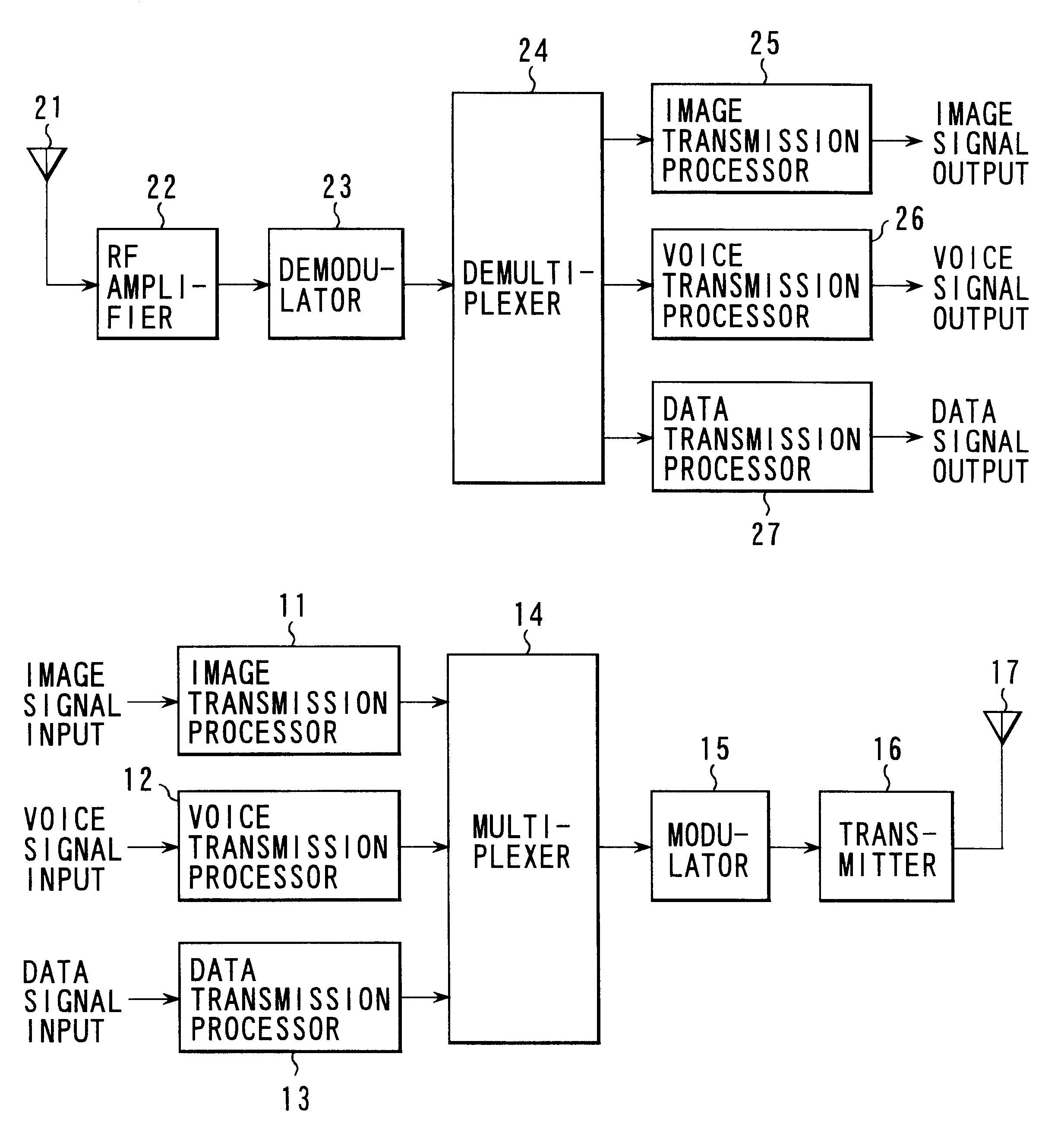
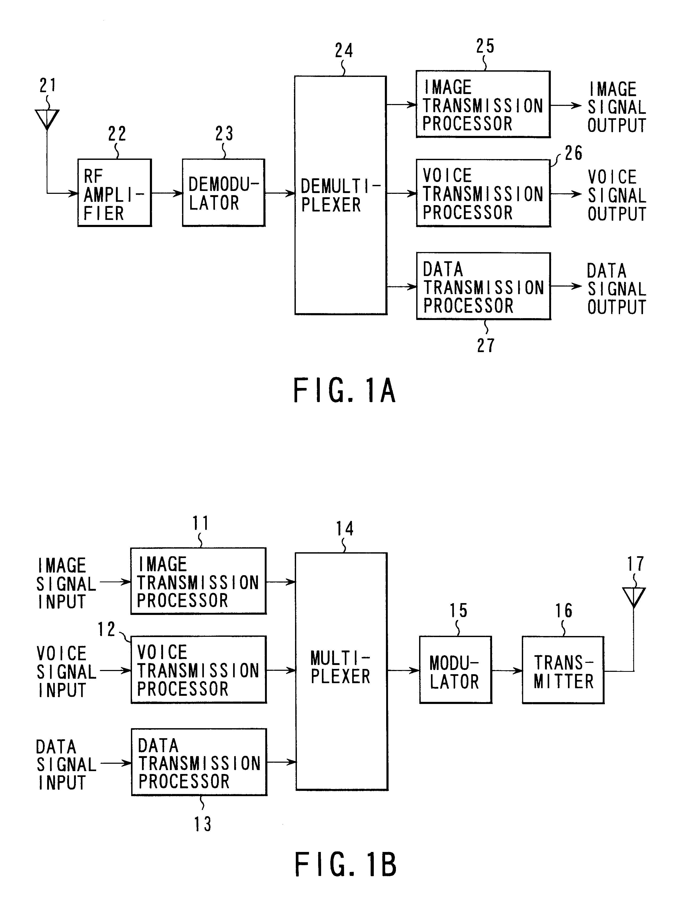
FIGS. 1A and 1B show a first embodiment of an information data multiplex transmission system according to the present invention. FIG. 1A shows a configuration of a transmitting device, and FIG. 1B shows a configuration of a receiving device.

In FIG. 1A, an image signal input, a voice signal input, and a data signal input are supplied to an image transmission processor 11, a voice transmission processor 12, and a data transmission processor 13, respectively. Each of the transmission processors 11 to 13 conducts conversion processing on its input data according to its predetermined format, extracts resultant data in response to a request from a multiplexe...

second embodiment

With reference to the first embodiment, the protection scheme of the header has been described. For transmitting information with a high quality in mobile communication, however, it is necessary to protect the payload field as well.

In a second embodiment of the present invention, suitable protection is effected on a plurality of kinds of information inserted in the payload field of a packet, such as three kinds of information, i.e., voice, data and image, without significantly changing the format of H.223. This will be hereafter described in detail.

First of all, as for computer data, the present embodiment proposes such a scheme as to add a shortened Reed-Solomon code over GF(2.sup.8) to the AL-SDU.

As for the voice, the present embodiment proposes such a scheme as to add an 8-bit CRC code to its control field (having one optional octet) and add a shortened Reed-Solomon code over GF(2.sup.8) to the AL-SDU and CRC.

As for the image, the present embodiment proposes such a scheme as to a...

third embodiment

FIG. 25 is a schematic configuration diagram of a MUX packet for description of a third embodiment of the present invention.

In the MUX packet, a 7-bit header, i.e., a control bit group, represented as C=[c(1), . . . , c(7)] with each element assuming a value of +1 or -1. In the control bit group, various kinds of control information, such as the number of bits of each kind in multiplexing the media information pieces of voice, data and image, are contained. Unless these control bits are recognized correctly on the receiving side, the multiplexed media information of voice, data and image cannot be separated and reproduced.

On the transmitting side, therefore, an 8-bit parity 1 represented as P=[p(1), . . . , p(8)] is. generated for the 7-bit control bit group according to an encoding rule of the BCH (15, 7). And for 15 bits obtained from the 7-bit control bit group C and the 8-bit parity 1P, 15-bit parity 2 represented as Q=[q(1), . . . , q(15)] is generated according to an encoding ...


PUM


Abstract

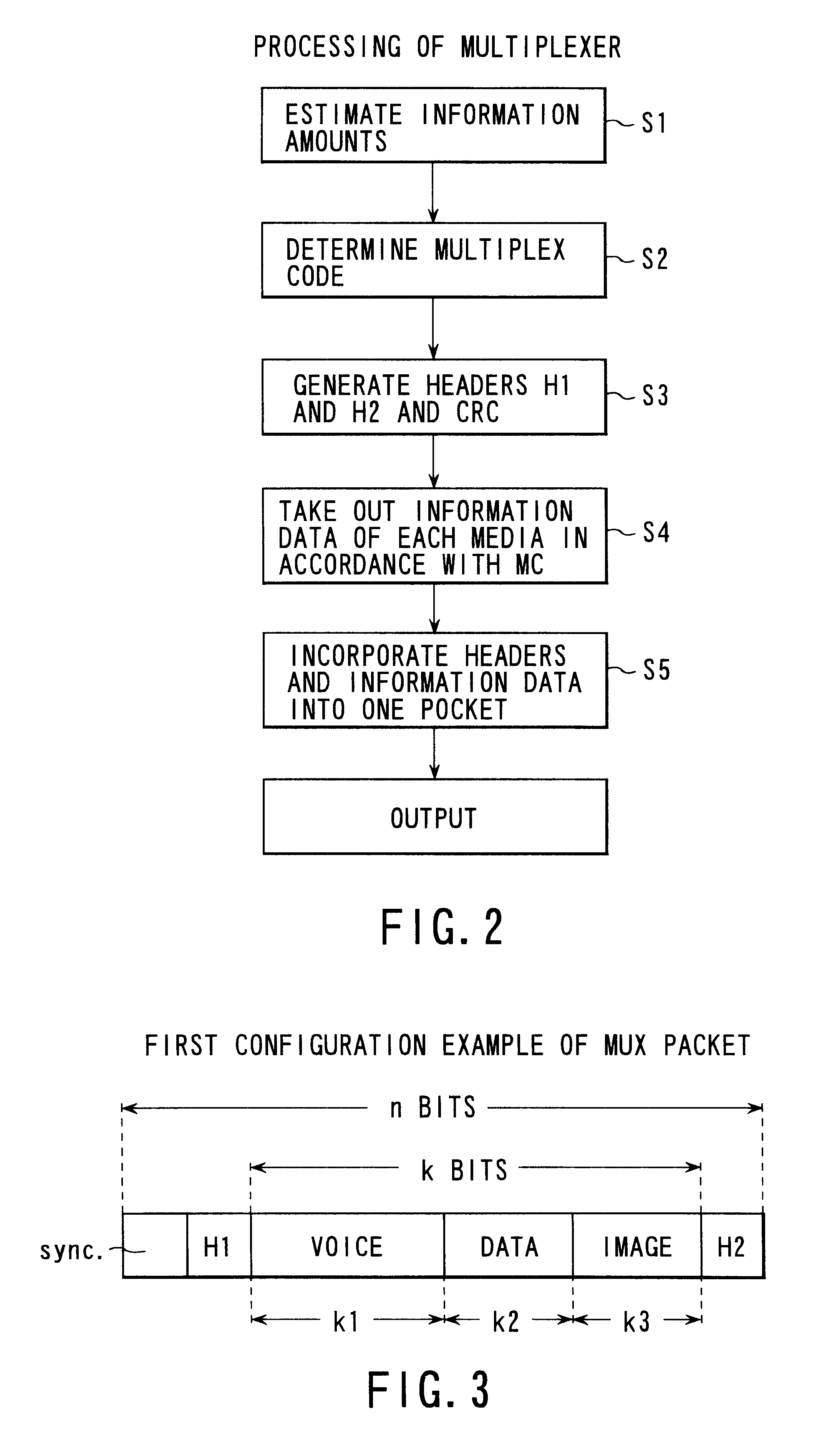
A multiplexing unit on the transmitting side estimates information amounts supplied from respective signal processing units, determines a multiplex code on the basis of respective information amounts, derives a parity of the first determined multiplex code to form a second multiplex code, adds a CRC to each of the multiplex codes to generate two headers H1 and H2, takes out information data of respective media according to the multiplex codes, incorporates the information data into a packet together with the two headers H1 and H2, and outputs the packet. If error correction of H1 is impossible on the receiving side, error correction decoding is conducted by using the header H2. If error correction of H2 is also impossible, error correction decoding is conducted collectively for H1 and H2.

Description

The present invention relates to a multimedia information data multiplex transmission system for putting information data of a plurality of kinds each having an arbitrary information content into a single packet and conducting multiplexed radio transmission, and its multiplexer and demultiplexer. The present invention further relates to an error correction encoder and decoder suitable for application to this system.For implementing radio multimedia, it is necessary to multiplex and transmit media information such as image data, voice data, additional data, and the like. Especially for giving and taking these kinds of information by using a mobile communication terminal, it is important that the information is made to be capable of being transmitted in a poor environment such as a multi-path fading environment.Heretofore, ITU-T recommendation H.223 has been standardized as a scheme concerning multimedia multiplexing. This scheme implements multimedia multiplexing of packet multiplexi...

Claims


Application Information

Patent Timeline
IPC IPC(8): H03M13/35H03M13/39H04L1/08H03M13/23H03M13/09H03M13/27H04L1/00H04L1/02H03M13/45H04L1/04H03M13/15H03M13/00H03M13/29H04N7/52H04N7/64H04N7/66H04L1/16H04L1/18G06F11/00G06F11/10H03M13/11H04J3/00H04J3/24H04N7/08H04N7/081H04N19/102H04N19/134H04N19/169H04N19/60H04N19/65H04N19/70H04N19/85H04N19/89H04N21/2383H04N21/438
CPCH03M13/00H03M13/09H03M13/1515H03M13/152H03M13/155H03M13/19H03M13/23H03M13/27H03M13/2957H03M13/356H03M13/3944H03M13/618H03M13/6362H04L1/0009H04L1/0041H04L1/005H04L1/0065H04L1/0066H04L1/0069H04L1/007H04L1/0083H04L1/04H04L1/08H04N7/52H04N21/2368H04N21/4341H04L1/0054H04L1/0057H04L1/0059H04L1/0071H04L1/18H04N21/23614H04N21/2383H04N21/4348H04N21/4382H04L1/00
Inventor TANAKA, HIROKAZUYAMASAKI, SHOICHIRO
Owner KK TOSHIBA
Learn More