Transducer featuring magnetic rotor concentrically arranged in relation to multi-phase coil

a technology of multi-phase coils and transducers, applied in the field of user interfaces, can solve the problems of poor mechanical feedback to users, large diameter, and large size of mechanical rollers, and achieve the effect of simple overall structur

Inactive Publication Date: 2002-11-19
NOKIA TECHNOLOGLES OY
View PDF7 Cites 9 Cited by
  • Summary
  • Abstract
  • Description
  • Claims
  • Application Information

AI Technical Summary

Benefits of technology

One advantage of the present invention is that there is no need to use an encoder with sliding contacts. The only wearing parts are bearings between the magnetic rotor and the multi-phase coil member. Another advantage is that the overall structure is quite simple.
is that there is no need to use an encoder with sliding contacts. The only wearing parts are bearings between the magnetic rotor and the multi-phase coil member. Another advantage is that the overall structure is quite simple.

Problems solved by technology

One problem with the roller known in the art is that it needs to use encoders with sliding contacts; and the size can also be a problem.
The mechanical encoder needs space for sliding contacts, and if the contacts are inside the roller wheel, the diameter becomes quite large.
If the encoder is outside the roller wheel, there are problems because of a long shaft (industrial design) and sealing.
The mechanical feedback to the user is poor in mechanical rollers.
It is not possible to control the behavior of the known roller by software.
However, the sliding contacts quickly wear; sliding contacts generate unwanted signals too that must be filtered; and the mechanical feedback to the user is passive and has to be generated by a mechanical wearing system.

Method used


Image

  • Transducer featuring magnetic rotor concentrically arranged in relation to multi-phase coil
  • Transducer featuring magnetic rotor concentrically arranged in relation to multi-phase coil
  • Transducer featuring magnetic rotor concentrically arranged in relation to multi-phase coil

Examples


Embodiment Construction

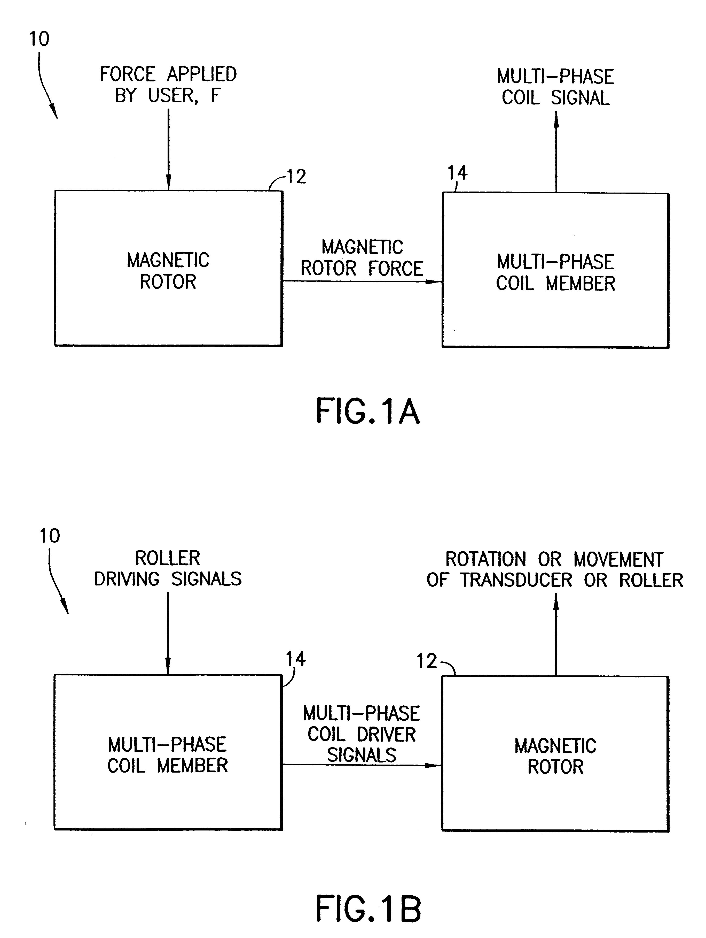
FIGS. 1A, 1B: The Basic Invention

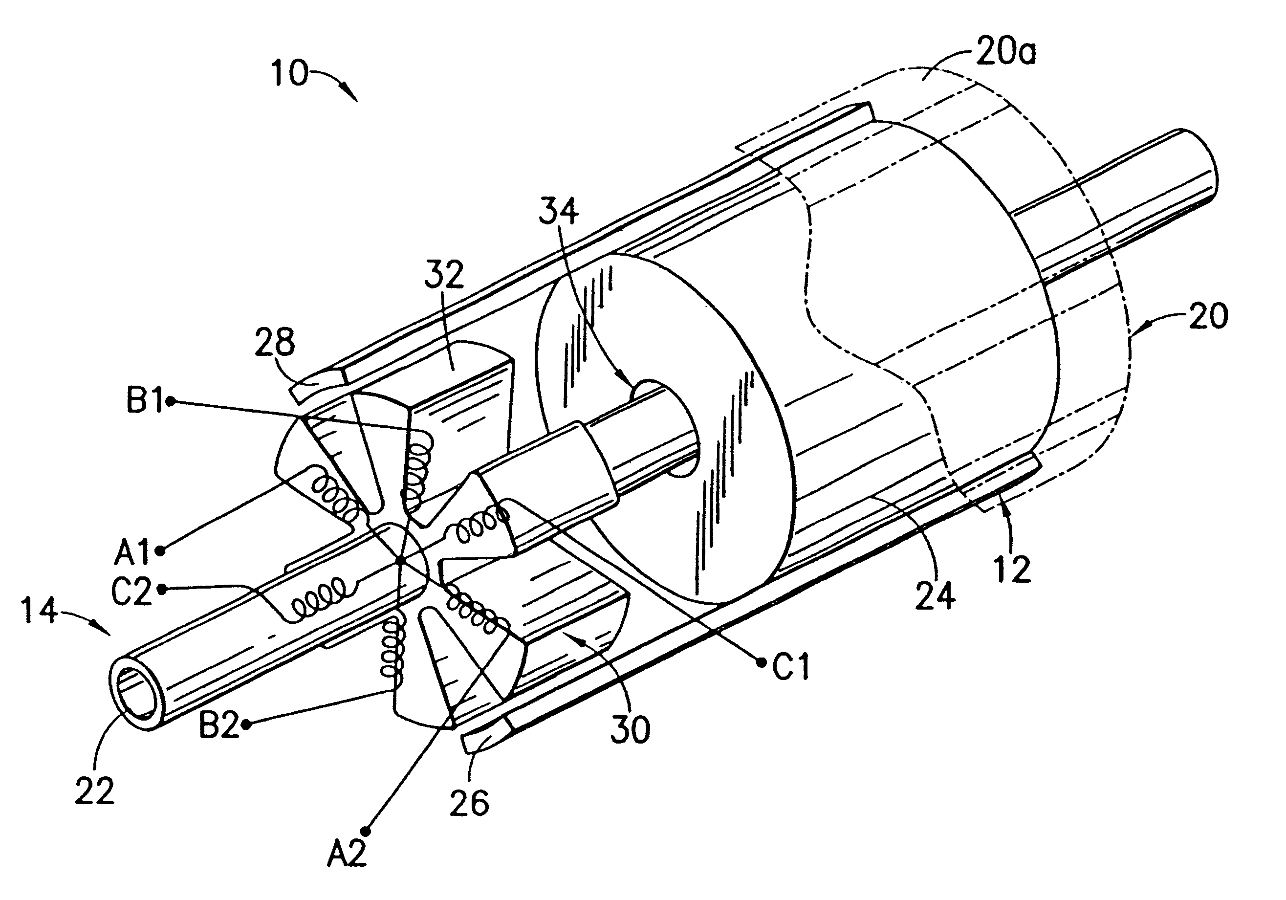
FIGS. 1A, 1B show the basic invention, which includes a transducer or roller generally indicated as 10 that may be used as a sensor of a force or as a driver for providing a force.

In FIG. 1A when used as a sensor, the transducer or roller 10 responds to a force F applied by a user, for providing a multi-phase coil signal containing information about the force applied by the user. The transducer or roller 10 has a magnetic rotor 12 in combination with a multi-phase coil member 14. The magnetic rotor 12 responds to the force F applied by the user, for providing a magnetic rotor force. The multi-phase coil member 14 responds to the magnetic rotor force, for providing a multi-phase coil signal containing information about the force F applied by the user. The force F applied by the user may include a rotational force applied by the user to a track ball (not shown) or any force applied by the user to a mouse (not shown) that causes the transducer or roller...


PUM


Abstract

A roller responds to a force applied by a user, for providing a multi-phase coil signal containing information about the force applied by the user. The roller has a magnetic rotor and a multi-phase coil member. The magnetic rotor responds to the force applied by the user, for providing a magnetic rotor force. The multi-phase coil member responds to the magnetic rotor force, for providing a multi-phase coil signal containing information about the force applied by the user. The force applied by the user may include a rotational force applied by the user to a track ball or any force applied by the user to a mouse that causes the roller to move or rotate. In this case, the multi-phase coil signal contains information about the force applied on the track ball or mouse by the user. The roller may also respond to roller driving signals, for example, from a host system or other circuitry, for rotating the roller about the main roller axis. In this case, the multi-phase coil member responds to the roller driving signals, for providing multi-phase coil driver signals. The magnetic rotor responds to the multi-phase coil driver signals, for rotating or moving the roller. The roller may be used as a part of mobile, office, factory or military equipment, such as a joystick.

Description

1. Field of InventionThe present invention relates to a user interface in mobile, office, factory or military equipment.2. Description of Related ArtData input devices having rollers are known in the art. One problem with the roller known in the art is that it needs to use encoders with sliding contacts; and the size can also be a problem. The mechanical encoder needs space for sliding contacts, and if the contacts are inside the roller wheel, the diameter becomes quite large. If the encoder is outside the roller wheel, there are problems because of a long shaft (industrial design) and sealing. The mechanical feedback to the user is poor in mechanical rollers. It is not possible to control the behavior of the known roller by software.Moreover, the mechanical roller known in the art has mechanical signal switching, and after filtering the signal is microprocessor compatible; and the level of the signal is independent of the speed of movement in practice. However, the sliding contacts...

Claims


Application Information

Patent Timeline
Patent Type & Authority Patents(United States)
IPC IPC(8): G06F3/033
CPCG06F3/033
Inventor KIRJANEN, JARI
Owner NOKIA TECHNOLOGLES OY
Why Eureka
Try Eureka