Pressure measuring device

Inactive Publication Date: 2002-11-19
WELCH ALLYN INC
View PDF25 Cites 25 Cited by
  • Summary
  • Abstract
  • Description
  • Claims
  • Application Information

AI Technical Summary

Benefits of technology

An advantage provided by the present invention is that a blood pressure measuring apparatus is provided in which a gage housing can be directly mounted to an inflatable sleeve without requiring any interconnecting hoses between the housing and the sleeve. That is to say, a sealed mechanical interconnection is provided between a gage housing and a sleeve permits fluid pressure changes within the sleeve to be immediately detected by mechanisms provided within the gage housing allowing a blood pressure measurement to be taken more readily than those previously known.
A further advantage is that previously known gage housings can be retrofitted to permit their attachment to the sleeve in a hoseless manner. Adapters can be provided which permit the suitable attachment, the adapters being attachable to the engagement port of the housing. The adapters can further be provided integrally with the engagement port to permit dedicated use with the socket on the sleeve.

Problems solved by technology

Typically, the above referred to movement mechanisms are quite intricate and complex, and are akin in terms of their manufacture and precision to Swiss watches.
As the spindle deflects axially in response to the inflation of the bellows, the bent spring part is also caused to deflect, thereby causing the and to twist.
In addition, any adjustments required after assembly of the above mechanisms, such as to null the pointer or adjust the sensitivity of the device, require substantial tear down or at least same undesired disassembly.

Method used


Image

  • Pressure measuring device
  • Pressure measuring device
  • Pressure measuring device

Examples


first embodiment

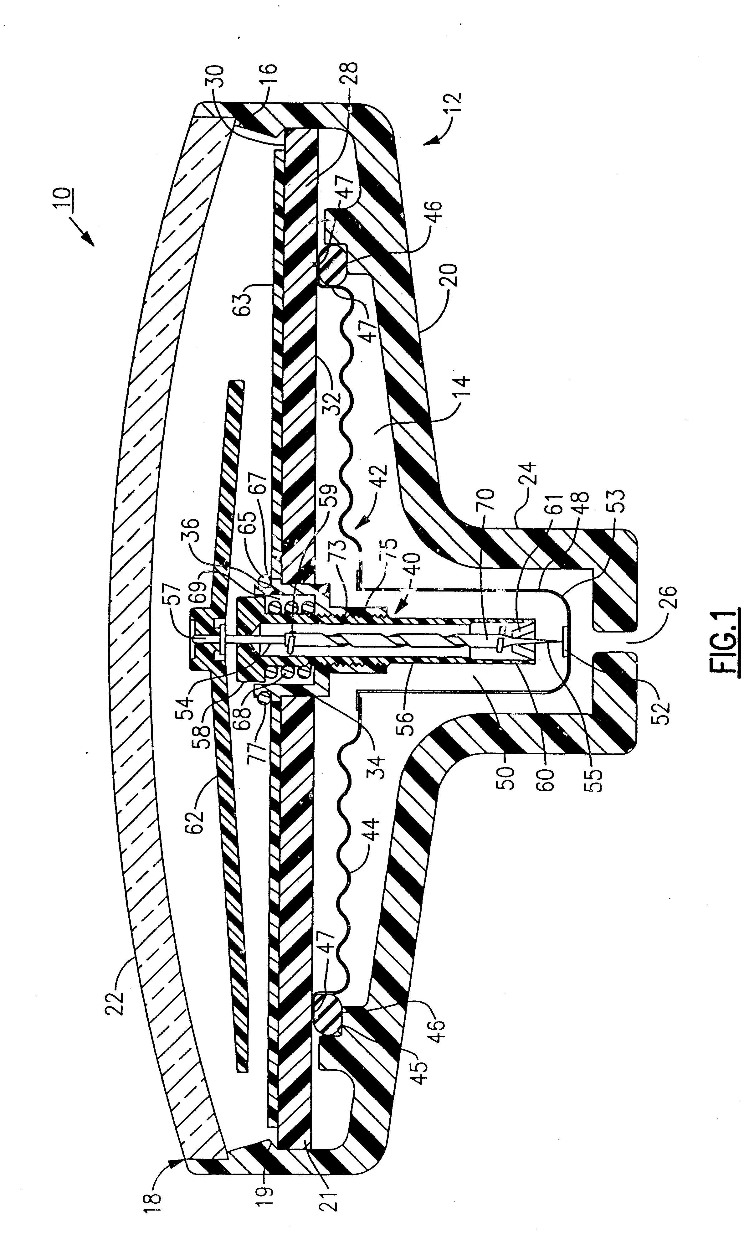
Referring to FIG. 1, there is shown a blood pressure measuring device or apparatus 10 made in accordance with the invention. The device 10 includes a substantially cylindrical gage housing 12 having an interior cavity 14 defined by a circumferential inner wall 16, an open top end 18, and a bottom end 20. A viewing window or bubble 22, made from glass, plastic, or other suitable transparent material is attached in a known manner to the open top end 18 of the gage housing 12. The bottom end 20 of the gage housing 12 has a diameter which inwardly tapers down to a narrow downwardly extending portion 24 having a bottom opening 26 serving as an inlet port for admitting a fluid. Preferably, the diameter of the narrow extending portion 24 is about one third of the diameter of the major portion of the housing 12, though it will be apparent from the following discussion that this parameter can be suitably varied depending upon the application.

The interior cavity 14 of the housing 12 is sized ...

second embodiment

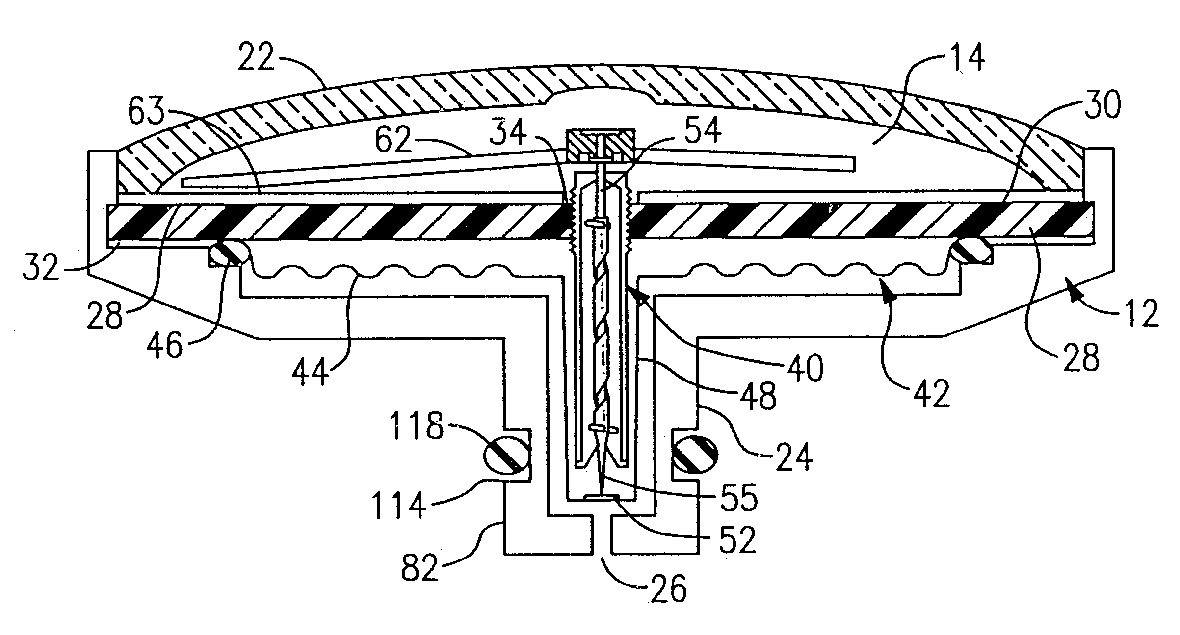
A housing design in accordance with a second embodiment is illustrated in FIG. 3. Similar parts are herein labeled with the same reference numerals for the sake of clarity. As in the preceding, the device includes a gage housing 12 having an interior cavity 14 sized for retaining a diaphragm assembly 42 which includes a diaphragm 44 having a series of wave-like surfaces 49 as well as a downwardly extending portion or pan 48. The device further includes a substantially horizontally disposed planar support plate 28, the housing 12 further having a downwardly extending narrowed portion 24. A movement mechanism 40 is disposed through a central opening 34 defined in the horizontal support plate 28 such that the bottom end 55 of an axially displace able shaft 54 of the mechanism is disposed in proximity to a hardened contact surface 52 of the pan 48 of the diaphragm assembly 42. The diaphragm 44 in the meantime is attached, but sealed, to the bottom facing side 32 of the horizontal suppor...

third embodiment

To further illustrate variations and referring to FIG. 4, a housing 12B made in accordance with the present invention includes a diaphragm 44B, which unlike the preceding embodiments, is a substantially vertical member having an overall width dimension that is considerably narrower than those previously described. As a result, a horizontal support plate is not required as in the preceding which is fitted to the circumferential inner wall 16 of the housing 12B.

Like the preceding embodiments, an outer edge 47B of the diaphragm 44B is sealed using an O-ring 46B or other sealing member which effectively clamps the outer edge to a shoulder of the a press-fitted sleeve 36B. The movement mechanism 40 is disposed essentially through a center opening in a press-fitted sleeve 36B and threaded into engagement therewith. The majority of the movement mechanism 40 is disposed within the cavity defined by the essentially vertical diaphragm 44B, the particular diaphragm of this embodiment having ve...


PUM


Abstract

A blood pressure measuring apparatus includes a sleeve having an inflatable interior, and gage housing having a movement mechanism disposed within said housing. The sleeve includes a socket which is sized to receive an engagement portion of the gage housing for directly attaching said gage housing to said sleeve to permit fluid interconnection between the interior of said inflatable sleeve and the interior of said housing without requiring a hose there between. The engagement portion of the gage housing can include an adapter to permit snap-fitting to the sleeve.

Description

FIELD OF THE INVENTIONThe invention relates to the field of measuring instruments, and more particularly to a shock-resistant gage housing for a pressure measuring device such as a sphygmomanometer.BACKGROUND OF THE INVENTIONPressure measuring devices such as sphygmomanometers, which are used to measure the arterial blood pressure of a patent, typically include a pneumatic bulb which inflates a pressure chamber of an attached sleeve that is fitted over a limb (i.e., an arm or a leg) of the patient. A diaphragm or bellows assembly, responsive to changes in fluid pressure of the pneumatic bulb and the sleeve pressure chamber, is positioned in a gage housing which is fluidly connected to the pressure chamber of the sleeve through flexible tubes or hoses. A pointer of a dial indicator is interconnected to the bellows assembly through a movement mechanism which is retained within the gage housing, whereby inflation of the bellows causes corresponding circumferential movement of the point...

Claims


Application Information

Patent Timeline
IPC IPC(8): A61B5/022
CPCA61B5/021A61B5/02141A61B5/022G01L7/082G01L19/0023G01L19/08G01L19/14G01L7/084
Inventor LIA, RAYMOND A.VIVENZIO, ROBERT L.DROMMS, RAYMOND P.
Owner WELCH ALLYN INC
Why Eureka
Try Eureka