
Apparatus for limiting noise in the zeros of RZ optical signals

a technology of optical signals and amplifiers, applied in the field of amplifiers for limiting noise in the " zeros " of optical rz signals, can solve the problems of distortion to which optical signals are subjected, and intensity modulation offers a solution that is not entirely satisfactory

Inactive Publication Date: 2002-09-24
AVANEX CORP
View PDF3 Cites 3 Cited by
  • Summary
  • Abstract
  • Description
  • Claims
  • Application Information

AI Technical Summary

Benefits of technology

It is also possible to provide a step of amplifying the signals before the offsetting step.

Problems solved by technology

One of the problems encountered in optical fiber transmission systems lies in the distortion to which the optical signals are subjected when they are generated, transmitted, or switched, or more generally, each time they are processed optically in the transmission system.
Unfortunately, intensity modulation offers a solution that is not entirely satisfactory, in particular in the "zeros" of RZ signals.

Method used


Image

  • Apparatus for limiting noise in the zeros of RZ optical signals
  • Apparatus for limiting noise in the zeros of RZ optical signals

Examples


Embodiment Construction

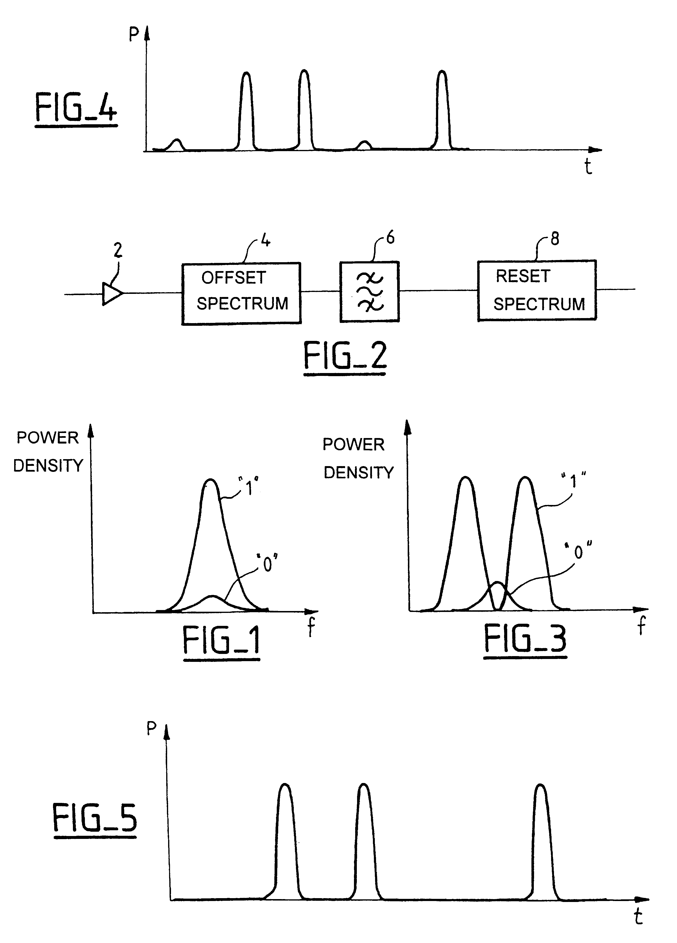
In order to reduce noise in zeros, the invention proposes to generate a spectrum offset between RZ signals as a function of their intensity, prior to filtering them. The spectrum offset and the filter are chosen so that the pulses corresponding to "ones" pass through the filter, and so that the filter reduces the amplitude of the "zeros". The invention thus makes it possible to reduce the noise in the "zeros" significantly. In order to apply a spectrum offset to the pulses as a function of their intensity, the invention proposes to trap the pulses propagating in the polarization directions of a birefringent optcial fiber. As indicated above, this trapping appears only above a certain intensity threshold.

FIG. 1 is a diagram showing the spectrum of the pulses of an RZ signal. Frequency is plotted along the x-axis, and power spectrum density is plotted up the y-axis. As is conventional for an RZ signal, the "ones" are represented by a pulse with a peak of high intensity, shown in fine ...


PUM


Abstract

The invention relates to apparatus for limiting noise in the "zeros" of optical RZ signals, the apparatus comprising a birefringent fiber for mutually spectrally offsetting the signals as a function of their intensity, and a filter for filtering the offset signals. The filter attenuates the pulses that correspond to "zeros", but passes the pulses that correspond to "ones". The invention makes it possible to limit the noise in the "zeros" of an RZ signal.

Description

The present invention relates to the field of optical fiber transmission, and more particular to optical regeneration for optical fiber transmission systems. It is particularly applicable to transmission systems for return-to-zero (RZ) signals, such as, for example, transmission systems for soliton signals. The RZ signal corresponding to a high logic value being transmitted is referred to as a "pulse" or a "one", and the absence of signal, corresponding to a low logic value being transmitted, is referred to as a "zero".It is known that soliton pulses or "solitons" can be transmitted in a portion of an optical fiber that has abnormal dispersion. Solitons are pulse signals of sech.sup.2 waveform. With such a pulse waveform, the non-linearity in the corresponding portion of the fiber compensates the dispersion of the optical signal. Soliton transmission can be modeled in known manner by the non-linear Schrodinger equation. Proposals have also been made for dispersion-managed soliton tr...

Claims


Application Information

Patent Timeline
Patent Type & Authority Patents(United States)
IPC IPC(8): H04B10/18H04B10/2507H04L25/02
CPCH04B10/25077
Inventor PINCEMIN, ERWANBIGO, SEBASTIEN
Owner AVANEX CORP
Learn More