
Ink jet recording apparatus using recording unit with ink cartridge having ink inducing element

a technology of ink inducing element and recording unit, which is applied in printing and other directions, can solve the problems of user separation, difficult to predict the situation on which the recording head or the ink cartridge is detached and mounted, and the recording head is difficult to receive ink from the ink cartridge. , to achieve the effect of preventing ink from leaking, low cost and high reliability

Inactive Publication Date: 2002-09-24
CANON KK
View PDF40 Cites 33 Cited by
  • Summary
  • Abstract
  • Description
  • Claims
  • Application Information

AI Technical Summary

Benefits of technology

is to provide an ink cartridge with low cost and high reliability which prevent ink from leaking therefrom and stably supply ink after detaching and connecting between a recording head and an ink cartridge.

Problems solved by technology

Furthermore, there is a possibility of that the user will separate them oftener than he or she have to do.
Therefore, it is difficult to predict the situation on which the recording head or the ink cartridge is detached and is mounted.
That is, the present inventors find that the recording head is difficult to receive the ink from the ink cartridge generally in the case of after connecting the ink cartridge with the recording head, again before the ink cartridge is used up.
In this situation, the ink flow to the recording head cannot be often recovered by an ejection recovery operation with the step of sucking ink out of ejection port of the recording head and thus it is difficult to consume the ink completely.
Under these conditions, consequently, undesirable recording state can be caused as a result of decreased amount of ink flow or the interrupted ink route.
In this document however, there is no suggestion to solve the problem of that the air gets into the ink cartridge during the period of performing the separation and the re-connection between the recording head and the ink cartridge.
Comparing with the conventional recording unit, however, a process of making the recording unit having the valve mechanism requires more cost of the production and more parts, and also the resulting product can be a large-sized one with a poor performance.

Method used


Image

  • Ink jet recording apparatus using recording unit with ink cartridge having ink inducing element
  • Ink jet recording apparatus using recording unit with ink cartridge having ink inducing element
  • Ink jet recording apparatus using recording unit with ink cartridge having ink inducing element

Examples


first embodiment

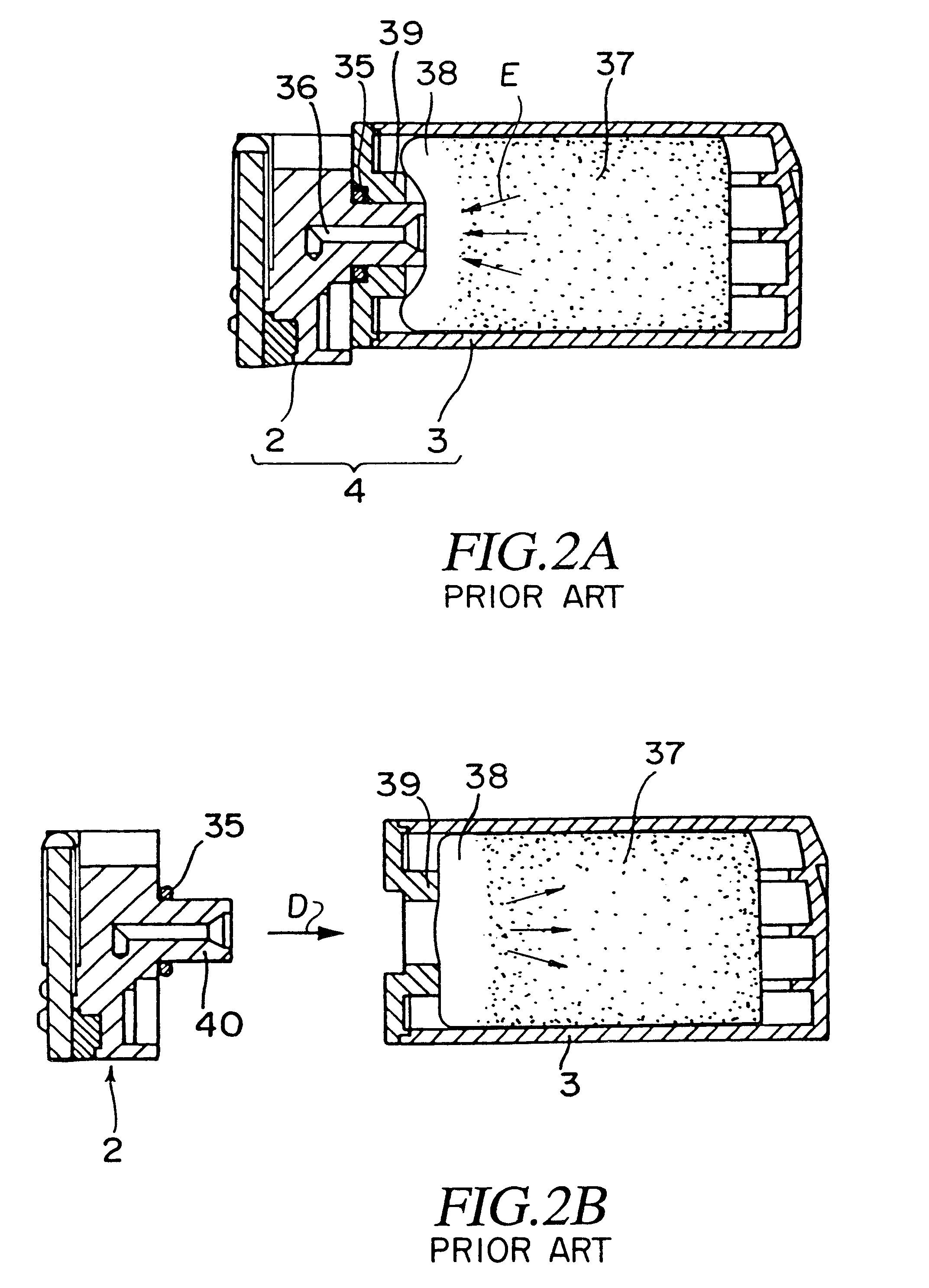
FIGS. 3A and 3B show cross sectional views of an ink-jet recording unit 4 as the present invention. The recording unit 4 is composed of two parts, a recording head 2 and an ink cartridge 3, which are easy to connect with each other as shown in FIG. 3B and also easy to take off from each other as shown in FIG. 3A.

The ink-jet recording head 2 has a filter 43 at an end of an ink-inlet portion 45 which functions as a connecting portion with the ink cartridge 3. The filter 43 has a plurality of pores that have a constant pore size and is responsible for trapping debris in an ink flow when the recording head is being connected with the ink cartridge 3. The pore size of the filter 43 is in the range as defined below. That is, the upper limit of the effective pore size is defined as a maximum effective diameter of the pore enough to prevent an inflow of the debris to the recording heads, which is depended on a size of the nozzles formed at the other end of the liquid passage in the recordin...

embodiment 3

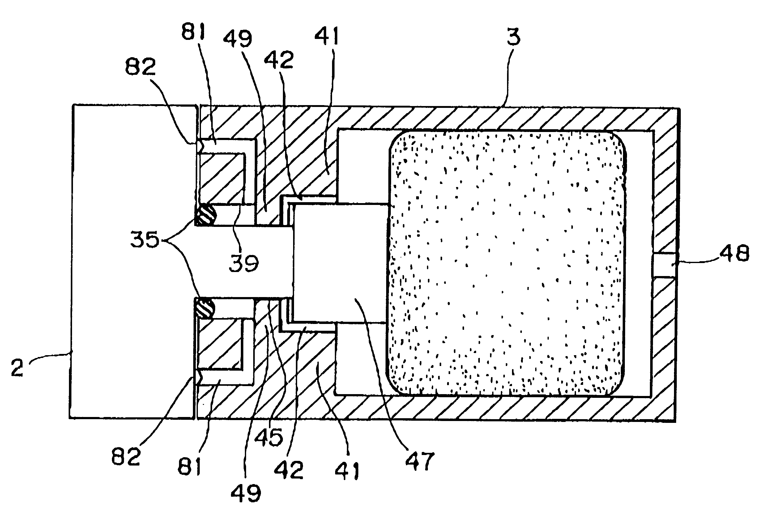
The first air path is the same one as that of That is, the first air path is composed of: a first spaced region formed by a plurality of the projection (i.e., ribs) 3a on the inner wall of the ink cartridge 3, which communicates to the external atmosphere through the air-communicating port 48; and a second spaced region formed by the grooves 42 between the ink-inducing element 47 and the surface of the supporting region 41.

The second air path is composed of a spaced region (i.e., a third spaced region) formed by at least one air-communicating port 81 (in the figure, two ports are shown) opened at the front side to be faced to the recording head. The air-communicating port 81 leads to a part of the ink-supply portion 39 where the ink-inlet portion 45 of the recording head 2 is inserted.

At the time of connecting the recording head 2 with the ink cartridge 3, an outer peripheral surface of the ink-inlet portion 45 of the recording head 2 is contacted with a corresponding inner periphe...


PUM


Abstract

An ink cartridge (3) including an ink reservoir portion having a porous member (37) for storing ink and an ink supply portion (39) has an ink inducing element (47) disposed between the ink reservoir portion and the ink supply portion (39). The ink inducing element (47) is made of bundle of fibers in which each fiber is disposed in parallel to the direction of ink supplying from the ink reservoir to the ink supply portion (39), and one end of the ink inducing element (47) is press-touched to the porous member (37).

Description

1. Field of the InventionThe present invention relates to an ink-jet recording apparatus, and more particularly to an ink cartridge (hereinafter also referred to as an ink tank) for storing ink to be supplied to an ink-jet head, a recording unit which integrally includes the ink cartridge and the ink-jet head, which are removably connected with each other, and the ink-jet recording apparatus on which the recording unit can be removably mounted. In the following description, the term "record" includes a meaning of printing characters, images or the like on cloth, paper, plastic sheet, or the like.2. Description of Related ArtSeveral types of recording apparatuses on which a recording head of one's own method such as: wire-dot method; thermal recording method; thermal-transfer method; and ink-jet method, is mounted, and which record characters, images or the like on a recording medium such as a paper, have been proposed. Among these methods, the ink-jet recording method is one of non-...

Claims


Application Information

Patent Timeline
Patent Type & Authority Patents(United States)
IPC IPC(8): B41J2/175
CPCB41J2/17513B41J2/1752B41J2/17523B41J2/17553
Inventor UJITA, TOSHIHIKOTAKENOUCHI, MASANORITSUKUDA, KEIICHIRO
Owner CANON KK
Learn More