
Fault detection and isolation in a synchronous optical network (SONET) and in a synchronous digital hierarchy (SDH) network

a technology of synchronous optical network and fault isolation, applied in data switching networks, instruments, frequency-division multiplexes, etc., can solve the problems of time-consuming and expensive method of fault isolation and dissemination of information to nes for the purpose of signal restoration, and nes do not retain any information about the fault location, etc., to reduce the effect of eliminating any difference in the behavior of ptes

Inactive Publication Date: 2002-09-17
AMERICAN TELEPHONE & TELEGRAPH CO
View PDF5 Cites 35 Cited by
  • Summary
  • Abstract
  • Description
  • Claims
  • Application Information

AI Technical Summary

Benefits of technology

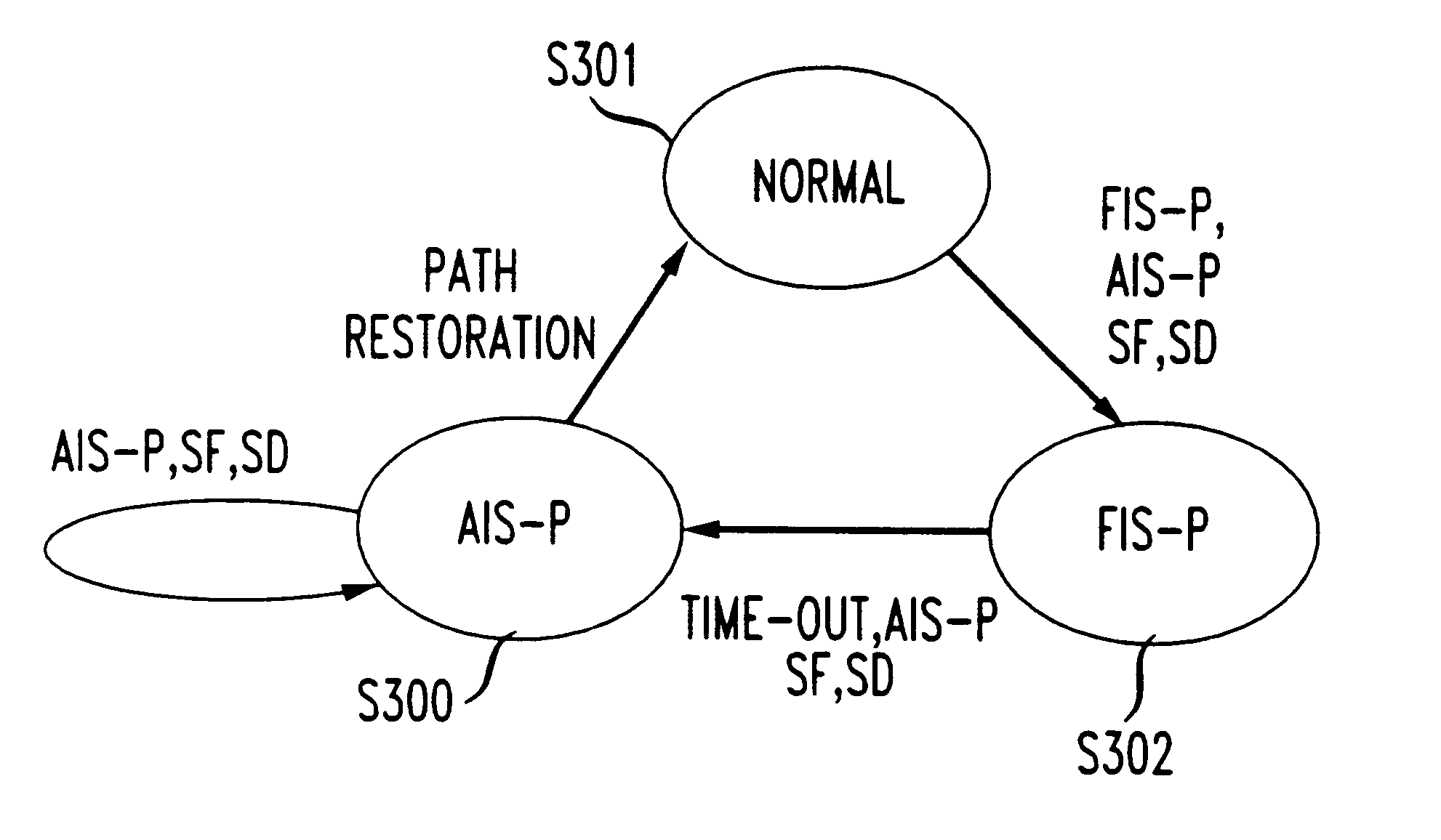
In the particular embodiments of the present invention described thus far, the PTEs that terminate the failed paths may behave slightly differently as compared with how they would behave in a conventional mode of operation. Accordingly, several variations of the basic invention are proposed below for reducing and / or eliminating any difference in the behavior of the PTEs. Although many variations exist, the variations discussed below comprise the "Time-Out" embodiments, the "FIS-P Termination" embodiments, and the "FIS-P AIS-P Flip" embodiments.

Problems solved by technology

Such a fault may be caused by a loss of signal (LOS), a loss of frame (LOF), or an excessive bit error rate (E-BER) in the link.
Moreover, NEs do not retain any information about the location of the fault.
Furthermore, in some network configurations, particularly those without rings, NEs such as ADMs adjacent to the fault location are not capable of restoring the failed or degraded signal through alternate routes.
This method of fault isolation and dissemination of the information to the NEs for the purpose of signal restoration is time consuming and expensive.

Method used


Image

  • Fault detection and isolation in a synchronous optical network (SONET) and in a synchronous digital hierarchy (SDH) network
  • Fault detection and isolation in a synchronous optical network (SONET) and in a synchronous digital hierarchy (SDH) network
  • Fault detection and isolation in a synchronous optical network (SONET) and in a synchronous digital hierarchy (SDH) network

Examples


Embodiment Construction

In some embodiments of the present invention, a DCS may insert an FIS-P when it detects a fault (if it is closest to the fault) and / or receives: an AIS-P on a SONET / SDH is path. All other DCSs downstream on the SONET / SDH path may thus receive the FIS-P and / or may pass the FIS-P through. After a predetermined time-out period (e.g., between 1 and 5 milliseconds, between 5 and 10 milliseconds, or between 10 and 20 milliseconds), the DCS closest to the fault location may stop sending the FIS-P and may begin to send an AIS-P on the downstream path. The downstream DCSs may recognize the change of the signal from an FIS-P to an AIS-P and may pass the AIS-P through.

According to some embodiments of the present invention, whether a downstream DCS inserts an FIS-P upon receiving an AIS-P from an upstream NE may depend upon whether the state of the SONET / SDH path changes from a normal state to an AIS-P or from an FIS-P to an AIS-P. Accordingly, the downstream DCSs may be configured such that th...


PUM


Abstract

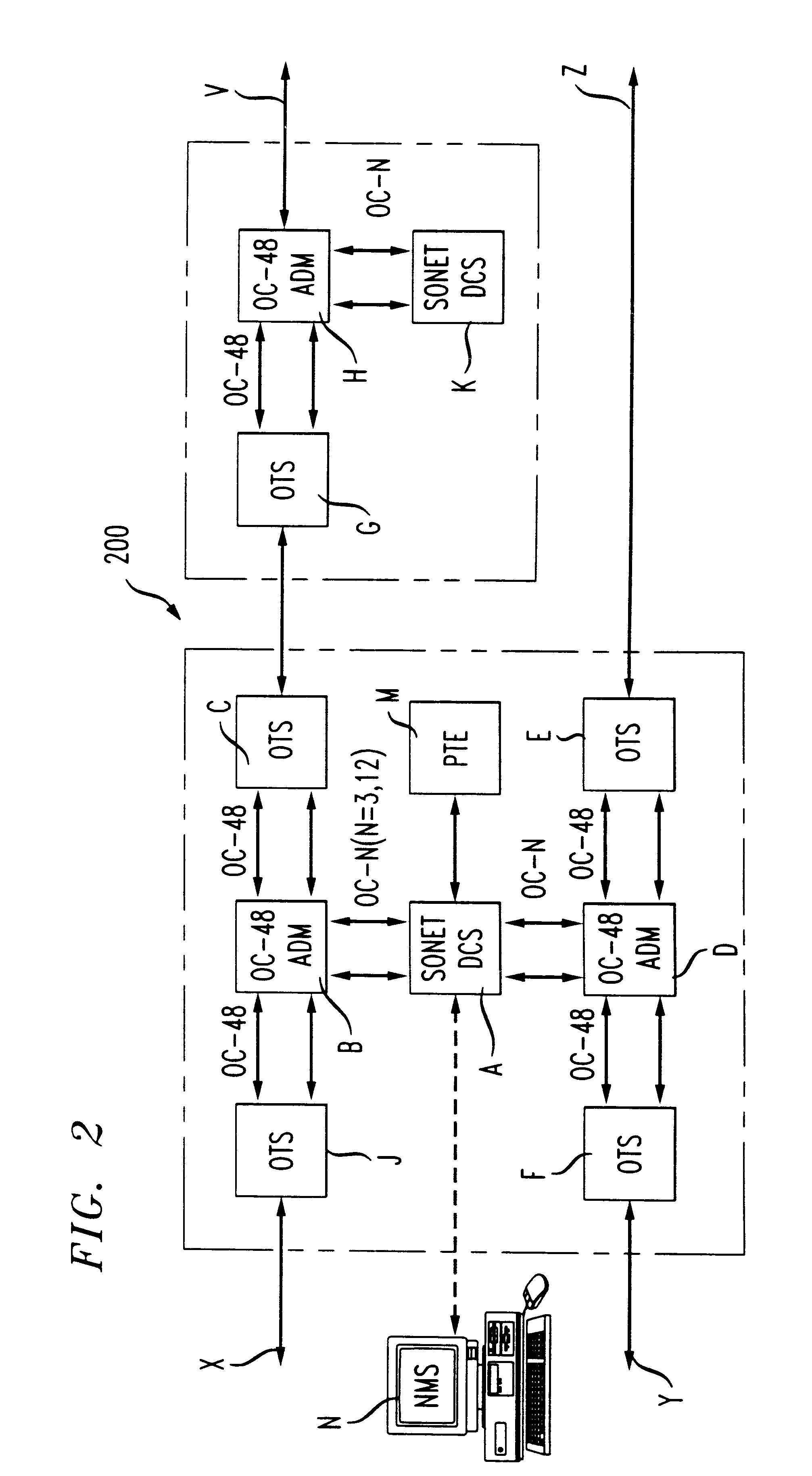
An in-band fault detection and isolation system and method for networks such as Synchronous Optical Network / Synchronous Digital Hierarchy (SONET / SDH) networks. Fault detection may be quickly and efficiently performed by a network without requiring modification to any add / drop multiplexers (ADMs) and / or without the involvement of an external network management system (NMS). To accomplish this without violating SONET / SDH standards, a new signal, called a fault isolation signal in the path (FIS-P), is proposed. The FIS-P may be used in lieu of an AIS-P to support special applications on certain digital cross connect (DCS)-to-DCS path segments. Moreover, the present invention may be implemented such that the behavior, of path terminating equipment (PTE) is unaffected.

Description

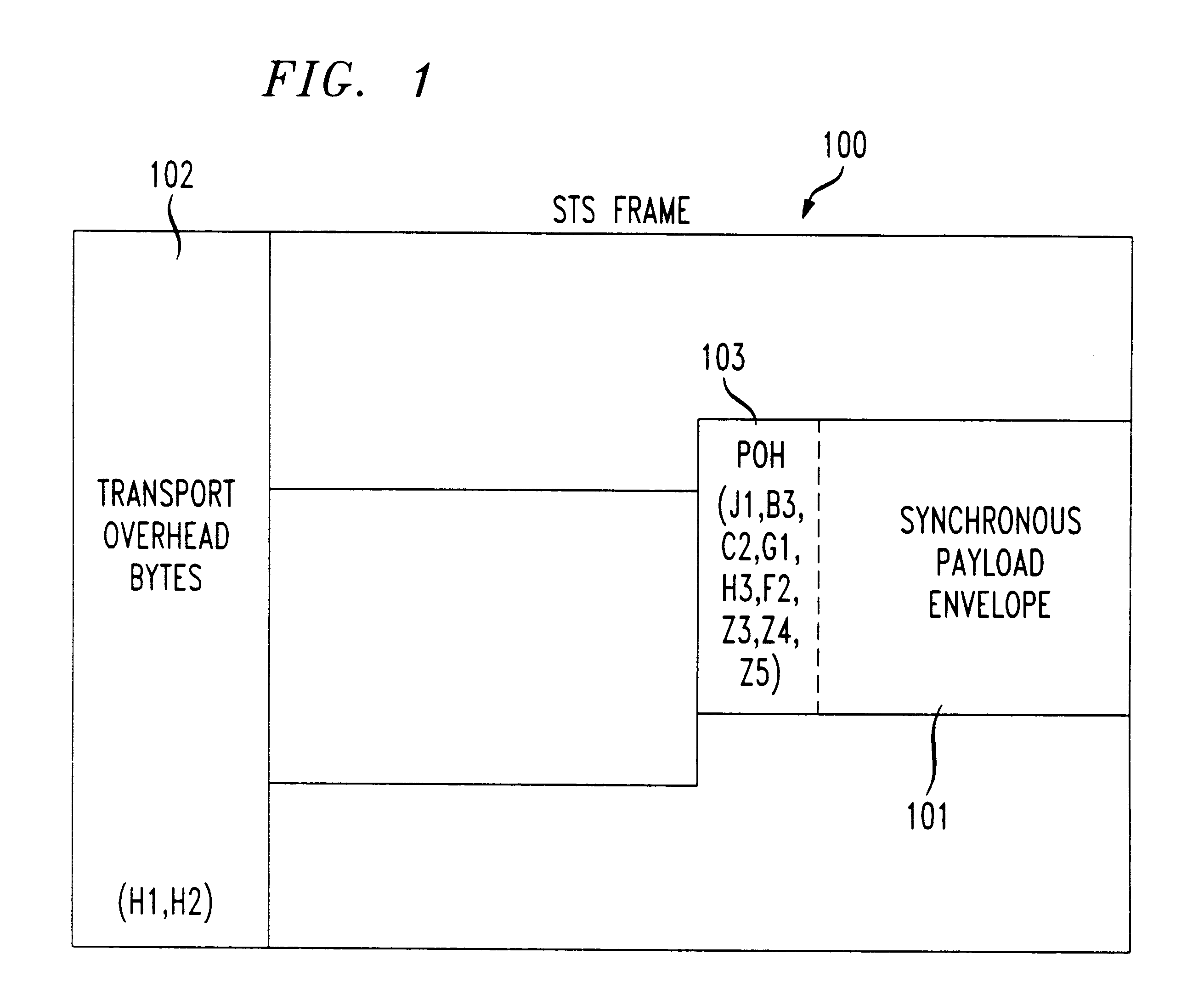
The present invention is directed generally to an in-band fault detection and isolation system and method for networks such as Synchronous Optical Network / Synchronous Digital Hierarchy (SONET / SDH) networks.In a Synchronous Optical Network / Synchronous Digital Hierarchy (SONET / SDH) network, signal fail (SF) and signal degrade (SD) faults are detected at a SONET / SDH network element (NE) that is nearest to the fault location. Such a fault may be caused by a loss of signal (LOS), a loss of frame (LOF), or an excessive bit error rate (E-BER) in the link. According to SONET / SDH standards, the nearest pair of SONET / SDH NEs inserts an Alarm Indication Signal (AIS-P) in the failed path upon detection of a fault so that all other NEs down the signal paths are informed that there is a fault in the upstream.Referring to FIG. 1, in a SONET / SDH network, data and overhead is transported in the format of a synchronous transport signal (STS) frame 100. Each STS frame 100 includes a synchronous payloa...

Claims


Application Information

Patent Timeline
IPC IPC(8): H04J3/14H04Q3/00H04Q11/04
CPCH04J3/14H04Q3/0075H04J2203/006
Inventor AFFERTON, THOMAS S.CHAUDHURI, SIDDOLLARD, PETER M.ZELINGHER, SIMON S.
Owner AMERICAN TELEPHONE & TELEGRAPH CO
Learn More