
Durable system for controlling the disposition of expended munitions fired at a target positioned close to the shooter

a technology for distributing and controlling the disposition of expended munitions, which is applied in the direction of bullet catchers, weapons, targets, etc., can solve the problems of inherently longer service life, flammability, and the need for replacement of conventional materials more often, so as to reduce the backsplatter of material dislodged, the screen is more durable, and the effect of reducing the backsplatter

Inactive Publication Date: 2002-09-10
US ARMY CORPS OF ENGINEERS
View PDF12 Cites 13 Cited by
  • Summary
  • Abstract
  • Description
  • Claims
  • Application Information

AI Technical Summary

Benefits of technology

An embodiment of the invention provides a screen in a target system that is durable, nonflammable, and reduces backsplatter of material dislodged by a bullet and ricochet of bullet fragments from a target or its backstop. The screen is more durable than conventional target systems such as those using wood or elastomers for screen material. Conventional materials not only need replacement more often but also are flammable when used with certain incendiary munitions. A novel feature of the screen of an embodiment of the present invention is a tapered end on each of the hard cementitious individual fill elements that is faced to the shooter.
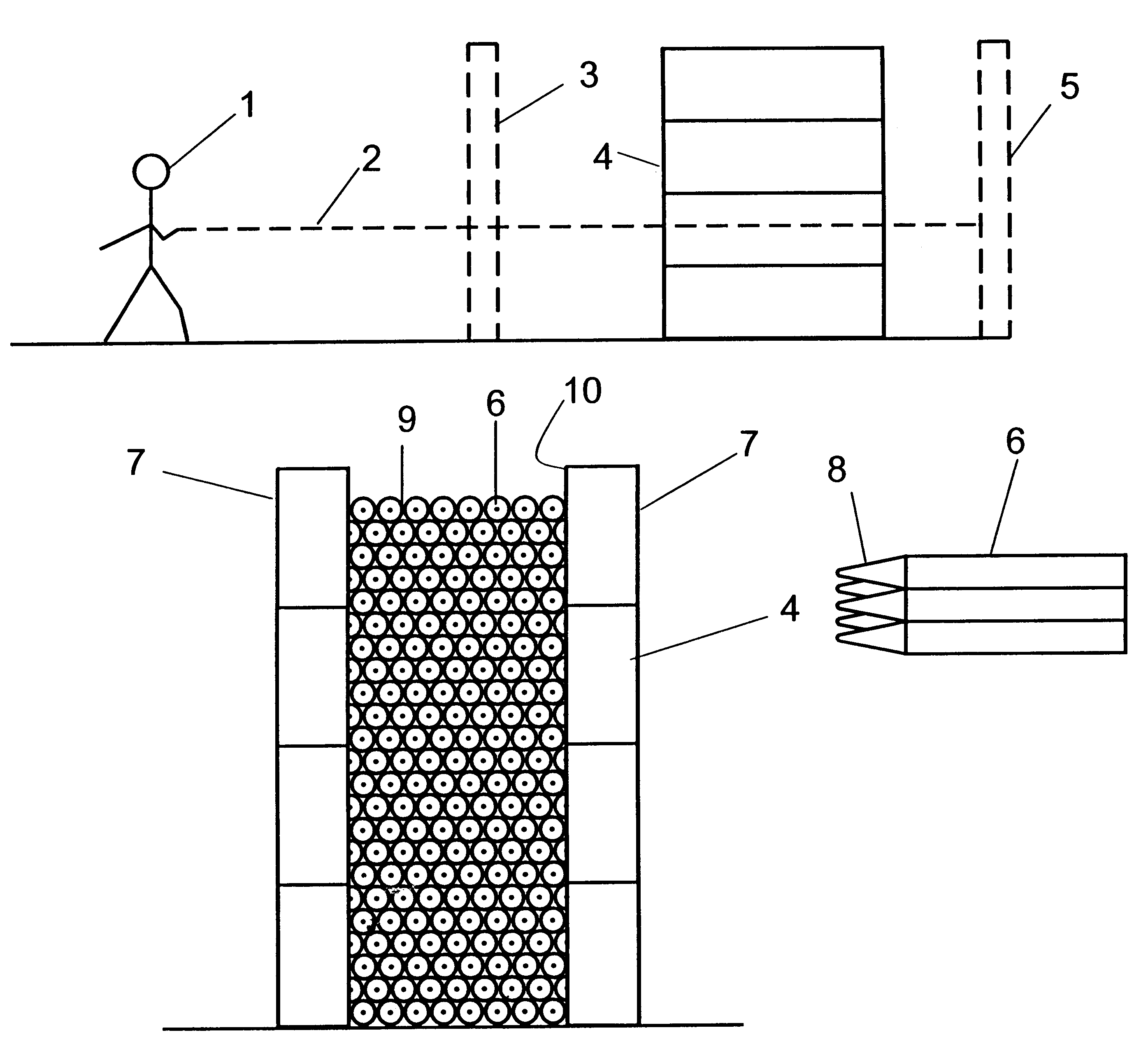
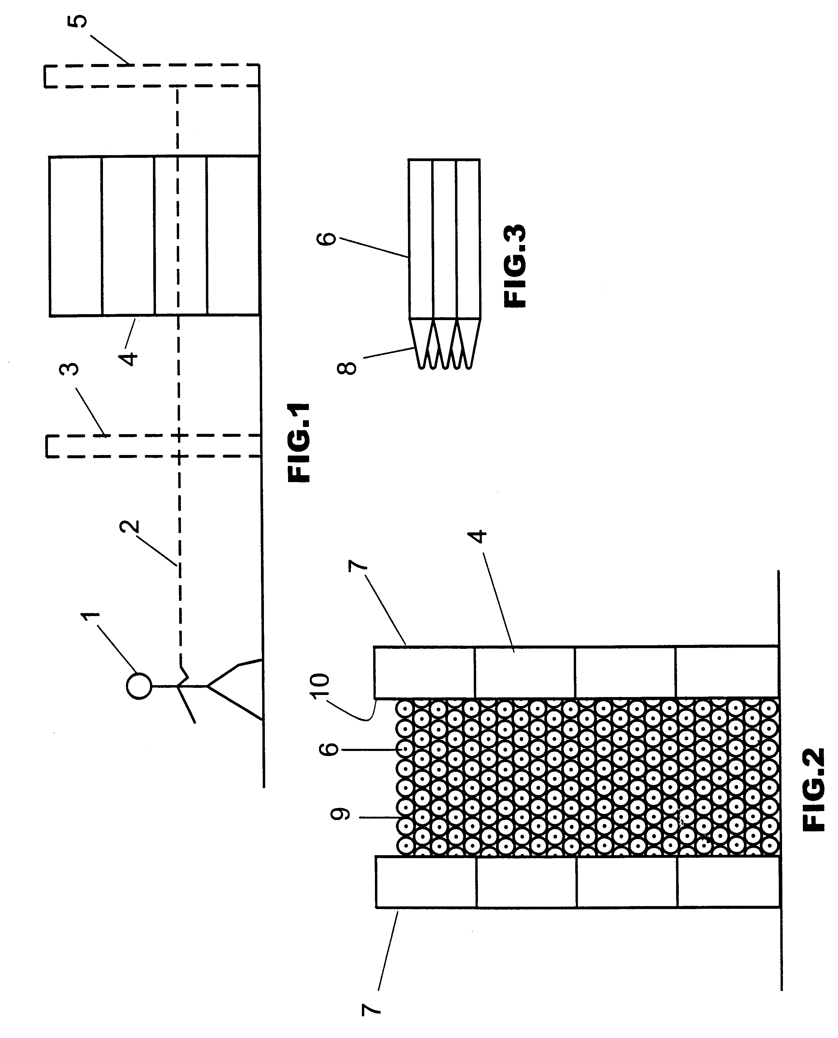
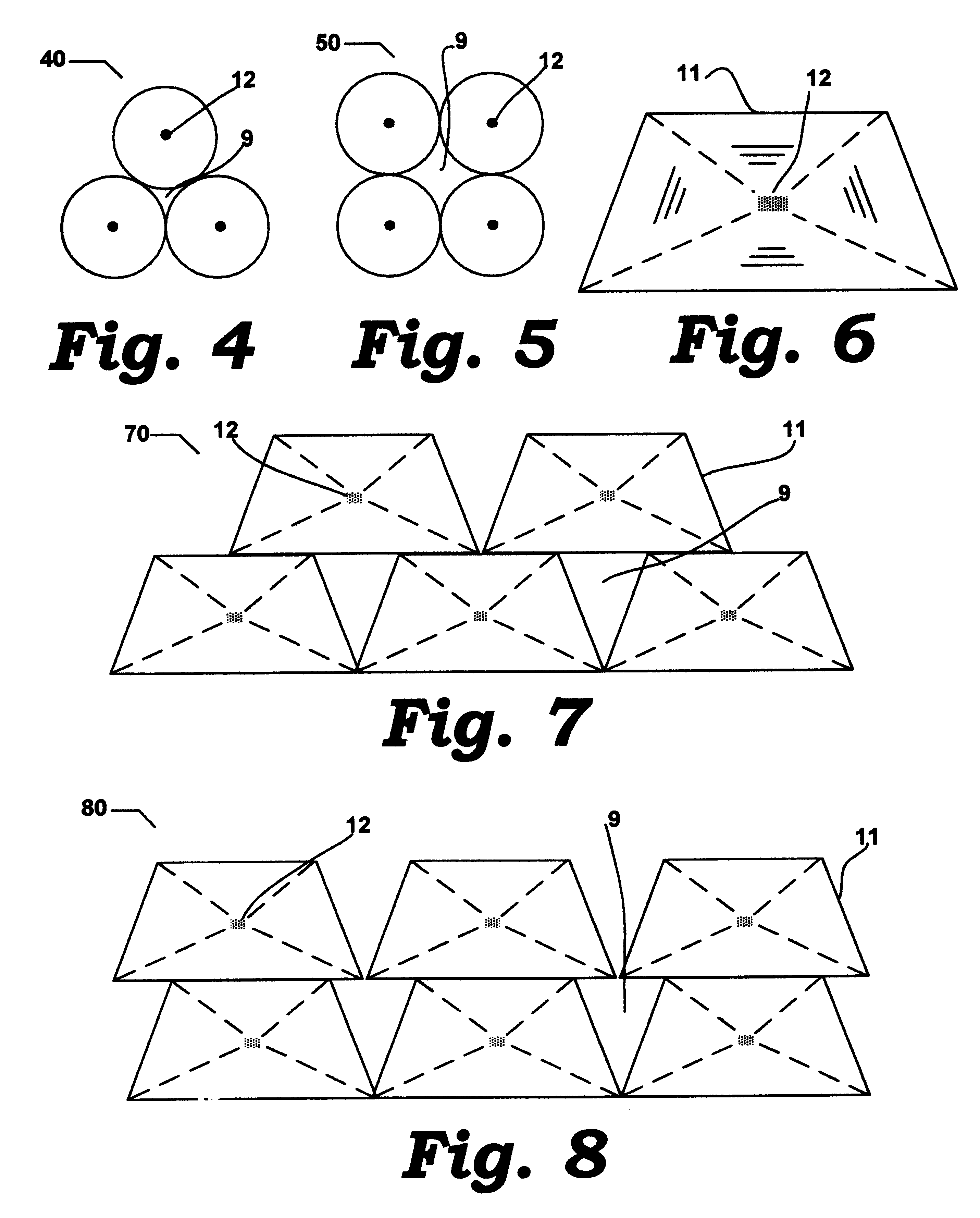
In one embodiment, the bullet screen is supported along its vertical edges by stacked blocks of appropriate strength to contain the combined weight of components that comprise the screen. The components may be cylinders having conical ends, the points of which are faced to the shooter. The cylinders may be stacked one above the other, i.e., in a "square" configuration, or offset between the underlying cylinders, i.e., in an "equilateral triangle" configuration. Another embodiment envisions the components having a trapezoidal cross section as opposed to the circular cross section of the cylinders. These trapezoidal components would be stacked one on top of the other or stacked offset much the same as the cylinders may be. The ends of these trapezoidal elements may be tapered toward a chisel end configuration with four planes tapering from the point to each of the sides of the trapezoid, much like a cold chisel. This tapered portion would face the shooter, thus offering the same advantages as the cylindrical components in determining the direction an impacting bullet would most likely take.
Either configuration provides openings along the sides of the screen's components for bullets and debris to pass. The direction that a bullet takes upon impact is influenced by initial impact at a necessarily shallow angle on the conical or wedge-shaped front of 30 the screen's components. This low impact angle serves to direct the bullet as well as any dislodged debris toward the rear of the components and into a backstop rather than ricocheting off the typically flat surface of a conventional durable hard target such as a masonry wall. Further, the bullet may experience multiple low angle impacts on multiple conical or wedge sections thus the screen may absorb much of its energy while also directing its flight to the backstop.
In a preferred embodiment, the components of the screen are fabricated from shock-absorbing, foamed, fiber-reinforced concrete. Further, the concrete may contain an excess of calcium hydroxide. Upon exposure to moisture, the excess calcium hydroxide produces a slightly alkaline leachate that interacts with the heavy metals, such as lead, that are components of the bullets impacting the screen. This interaction stabilizes any heavy metal embedded in the screen, immobilizing it and preventing it from leaching into the groundwater. A further advantage of the screen is that it requires little maintenance, e.g., it requires no coatings to deter rot or insect damage. Because it is impervious to natural erosion and constructed of durable materials, it has an inherently longer service life. Finally, the screen may be used in applications that use incendiary, deflagrating or tracer munitions on the range because it is nonflammable. Other materials, such as wood or elastomers, may be used in building bullet traps where fire hazards are low and durability is of secondary importance.

Problems solved by technology

Conventional materials not only need replacement more often but also are flammable when used with certain incendiary munitions.
Further, the bullet may experience multiple low angle impacts on multiple conical or wedge sections thus the screen may absorb much of its energy while also directing its flight to the backstop.
Because it is impervious to natural erosion and constructed of durable materials, it has an inherently longer service life.

Method used


Image

  • Durable system for controlling the disposition of expended munitions fired at a target positioned close to the shooter
  • Durable system for controlling the disposition of expended munitions fired at a target positioned close to the shooter
  • Durable system for controlling the disposition of expended munitions fired at a target positioned close to the shooter

Examples


Embodiment Construction

Refer to FIG. 1. A shooter 1 fires a projectile (not separately shown), such as a bullet, along a trajectory 2. The projectile may pass through a target 3 before entering a screen 4 representing a preferred embodiment of the present invention. Should the projectile, or parts thereof, and any debris dislodged from the elements of the screen pass as reduced energy projectiles through voids provided in the screen, these projectiles and debris may hit a backstop 5. Further, if enough energy has been retained by these projectiles and debris they may rebound from the backstop and hit the rear of the screen 4 where they may embed in elements of the screen 4 or fall harmlessly to the bottom of the space between the rear of the screen 4 and the backstop 5.

Refer to FIG. 6, depicting an end view of an alternative trapezoidal cross section 11 for the internal elements of the screen 4. These trapezoidal cross section elements 11 may be stacked in an equilateral triangle configuration 70 as shown...


PUM


Abstract

In a shooting range for training personnel in the use of firearms, a bullet trap that prevents rebounding bullets or flying debris from injuring shooters, has a central section of stacked cylindrical logs, or logs having a trapezoidal cross section, supported by stacked rectangular supporting blocks on each side. The stacked cylindrical logs have conical end sections at the end facing the shooter. These conical end sections direct incoming bullets to passageways between the cylindrical logs. Bullets passing through these passageways then strike a backstop panel. In a preferred embodiment, both the cylindrical logs and the backstop panel are made of shock-absorbing foamed fiber-reinforced concrete.

Description

I. BACKGROUND OF THE INVENTION1. Field of the InventionThis invention relates to a system that permits an operator to fire heavy caliber firearms, e.g., 0.50 caliber, at short ranges with reduced backsplatter of target material and ricocheting bullet fragments.2. Prior ArtBullet screens and traps used on firing ranges are known to the art. U.S. Pat. No. 4,821,620 discloses an anti-spatter screen made of rubber-like material adapted to self-closing is secured to the front face of a deflector plate. U.S. Pat. No. 5,564,712 discloses a bullet trap for indoor shooting with small arms using a vertically-suspended rubber curtain and a vertically-suspended steel impact plate. U.S. Pat. No. 5,486,008 describes a bullet trap having a passageway between upper and lower boundary walls converging on a deceleration chamber. U.S. Pat. No. 5,718,434 discloses a bullet trap for pistol and rifle ranges having one or more deflecting plates having curved sections which direct bullets toward a back wal...

Claims


Application Information

Patent Timeline
IPC IPC(8): F41J1/00F41J1/12F41J13/00
CPCF41J13/00
Inventor MALONE, PHILIP GARCINWEISS, JR., CHARLES ARTHURHUNTSMAN, BRAD LESLIEHUNTSMAN, BRENT ELLIOT
Owner US ARMY CORPS OF ENGINEERS
Learn More