
Advanced dual-flush valve

a technology of flush valve and valve body, which is applied in the direction of valve operating means/releasing devices, engine components, mechanical equipment, etc., can solve the problems of affecting the operation of the valve, the valve assembly is rendered useless for taller toilet tanks, and the mounting is also a problem

Inactive Publication Date: 2002-09-03
FLUIDMASTER
View PDF22 Cites 34 Cited by
  • Summary
  • Abstract
  • Description
  • Claims
  • Application Information

AI Technical Summary

Problems solved by technology

This was a cumbersome procedure which had to be carried out with each installation.
Unfortunately, once the shaft was cut, the valve assembly was rendered useless for taller toilet tanks.
Mounting has also been a problem in tanks having mounting holes slightly misaligned.
There has been no radial adjustability in prior flush valves to accommodate these toilets.
This structure has facilitated the passage of water into the hollow float thereby decreasing the buoyancy of the float during the flushing operation and prematurely closing the flush valve.

Method used


Image

  • Advanced dual-flush valve
  • Advanced dual-flush valve
  • Advanced dual-flush valve

Examples


Embodiment Construction

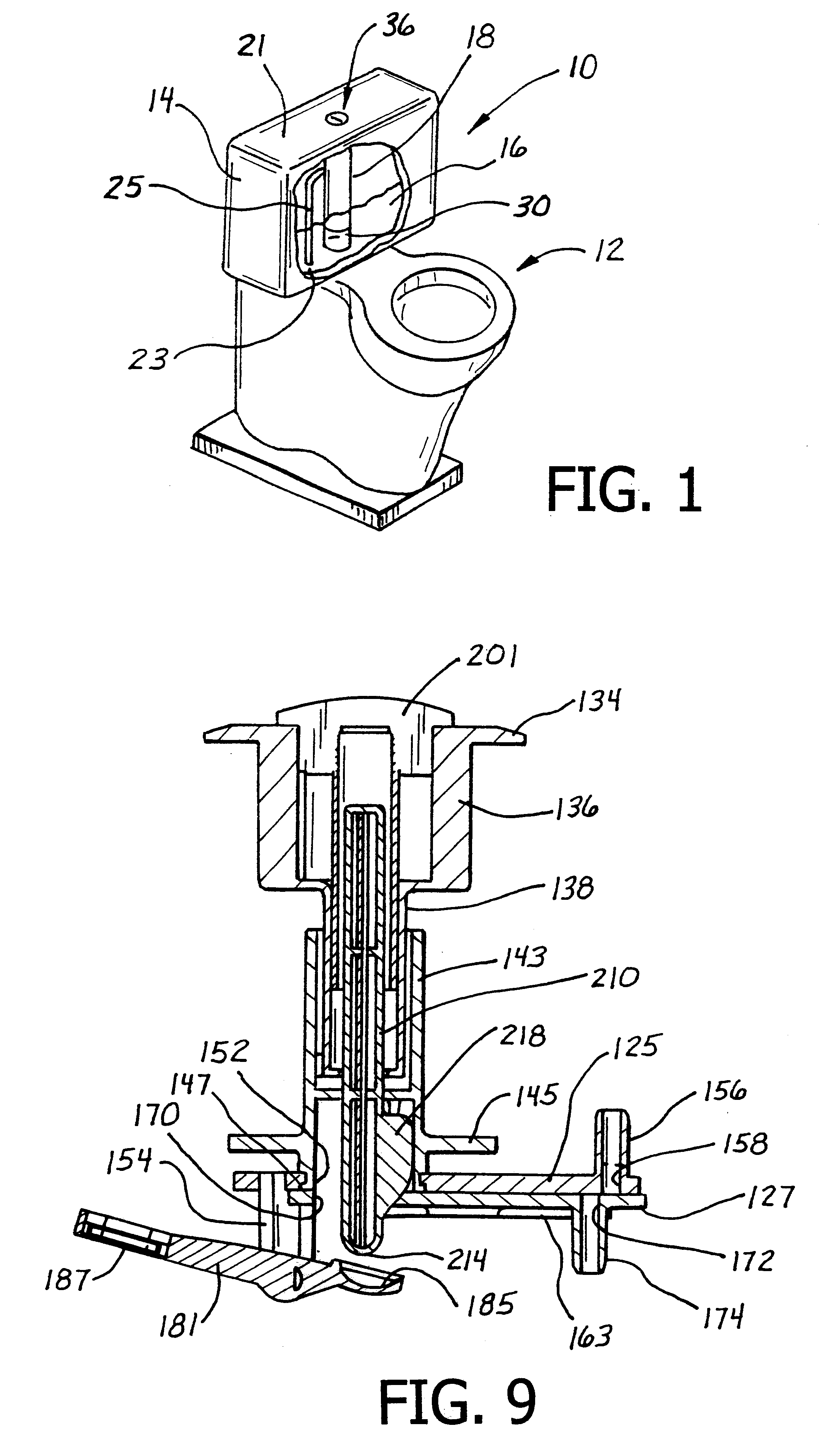
A toilet is illustrated in FIG. 1 and designated generally by the reference numeral 10. The toilet 10 includes a bowl 12 which is adapted to receive liquid and solid waste. A tank 14 is typically mounted above the bowl 12 and forms a reservoir for water 16 used to flush the bowl 12. A flush valve assembly 18 is mounted between a top 21 and a bottom 23 of the tank 14. The flush valve assembly 18 includes a pressure tube 25 which extends into the water 16 as described in greater detail below.

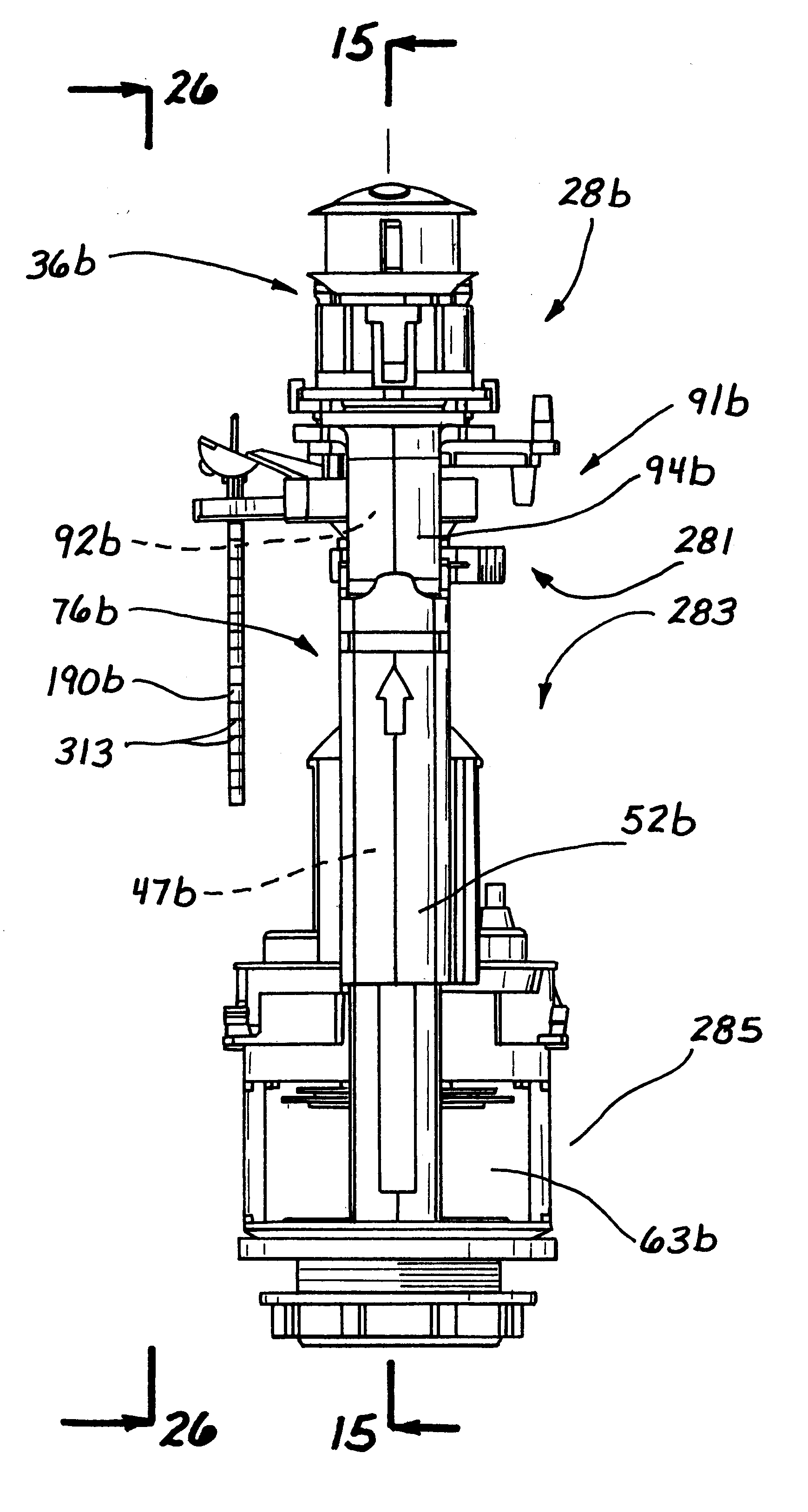
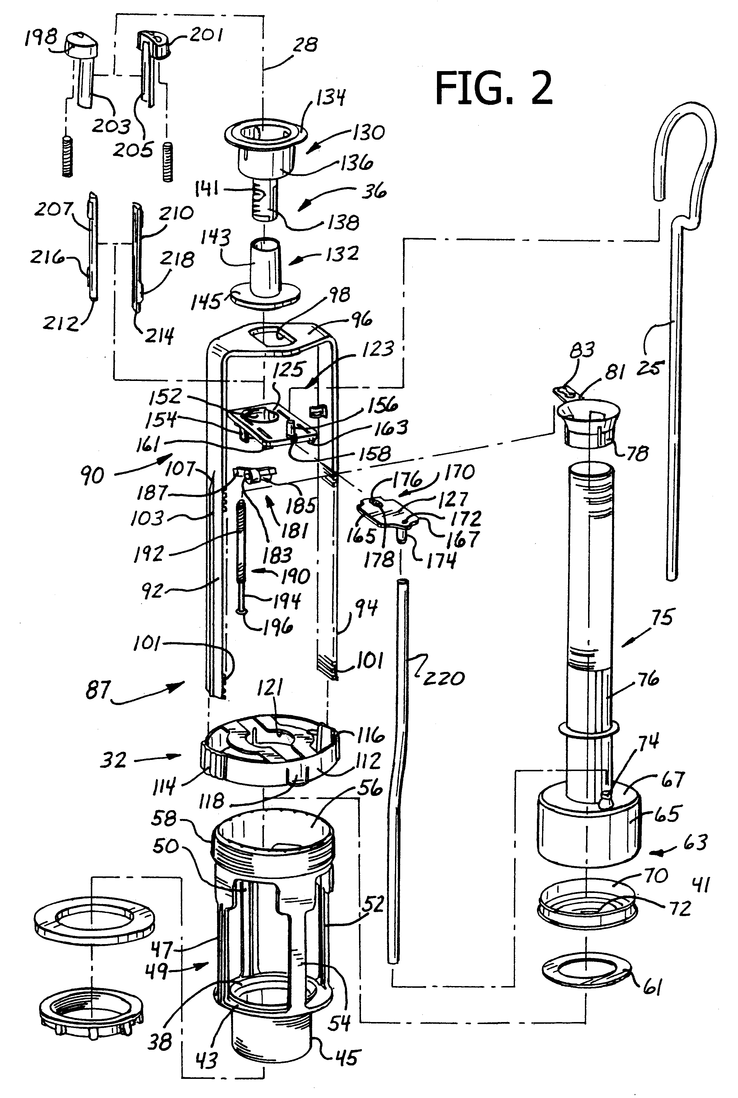
An exploded view of the flush valve assembly is illustrated in FIG. 2 with assembled views presented in FIGS. 3 and 4. From these views, it can be seen that the flush valve assembly 18 of a preferred embodiment has an axis 28 and includes generally a flush valve 30, an axial adjustment structure 32, a slide mechanism 34, and a selector assembly 36. In operation, the flush valve 30 releases water from the tank 14 into the bowl 12 in response to the operation of the selector assembly 36. Depending u...


PUM


Abstract

A flush valve is adapted to be mounted in the tank of a toilet and includes a selector assembly and a flush valve. The selector assembly is accessible from outside the toilet and provides for initiation of the flushing operation and an alternative choice between a larger flush water volume and a smaller flush water volume. A support structure provides for both axial and radial movement of the selector assembly relative to the flush valve in order to facilitate mounting and aligning of the flush valve assembly. A slide mechanism provides for variation of at least the smaller flush water volume.

Description

1. Field of the InventionThis invention relates generally to toilet flush valves and, more specifically, to valves providing alternative flush water volumes.2. Discussion of the Prior ArtToilets typically include a bowl which is adapted to receive liquid and solid waste, and a tank which provides a reservoir of water for flushing the waste from the bowl. Apparatus which is commonly mounted in the tank includes a flush valve assembly which is operable by the user to initiate the flushing of the bowl. A fill valve is also commonly mounted in the tank to refill the tank with a predetermined amount of water to be used in the next flushing operation.Flush valve assemblies can vary considerably in their complexity, but typically include a flush valve, a float and an actuation mechanism. By operation of the actuation mechanism, the flush valve opens to release water from the tank into the bowl and closes when the float reaches a predetermined level indicative of the amount of water left in...

Claims


Application Information

Patent Timeline
Patent Type & Authority Patents(United States)
IPC IPC(8): F16K31/26F16K31/18F16K47/08F16K47/00E03D1/30E03D1/14F16K31/44
CPCE03D1/142E03D5/02F16K31/26F16K47/08E03D5/09
Inventor HAN, JOSEPHMCKAY, JOHNHAGGSTROM, TRACY JAMESMAIWANDI, FARID
Owner FLUIDMASTER
Learn More