Mounting structure with improved stiffness characteristics

a technology of stiffness and mounting structure, applied in the direction of roofs, wing accessories, transportation and packaging, etc., can solve the problems of increasing the overall weight and cost of the vehicle, affecting fuel economy, and affecting the use of fuel economy

Inactive Publication Date: 2002-08-27
FORD GLOBAL TECH LLC
View PDF16 Cites 7 Cited by
  • Summary
  • Abstract
  • Description
  • Claims
  • Application Information

AI Technical Summary

Benefits of technology

It is a second object of the present invention to provide a mounting structure having improved stiffness characteristics in certain localized areas which are critical to the performance of the mounting structure.
It is a third object of the present invention to provide a mounting structure which operatively supports a vehicle door, and which improves certain performance characteristics of the door.
It is a fourth object of the present invention to provide a method for increasing the stiffness of a mounting structure which does not undesirably increase the overall weight and cost of the mounting structure.
According to a first aspect of the present invention, a mounting structure is provided. The mounting structure includes a first region on which a component is selectively mounted and a bead which is integrally formed within the structure and which substantially circumscribes the region, the bead being effective to stiffen the mounting structure.
According to a second aspect of the present invention, a method is provided for increasing the stiffness of a mounting structure on which a component is selectively attached. The method includes the steps of determining a region on which the component is selectively mounted; and forming a continuous bead within the mounting structure and around the region, thereby increasing the stiffness of the mounting structure.

Problems solved by technology

These types of methods suffer from some drawbacks.
For instance, the additional materials or structures used by these methods undesirably increase the overall weight and cost of the vehicle and adversely effect fuel economy.
Furthermore, the determination of the precise locations in which the materials should be added is typically performed on a "trial and error" basis.
This "trial and error" procedure requires a significant amount of time before yielding an optimized result, and may consume an excessive amount of material and / or prototypes.

Method used


Image

  • Mounting structure with improved stiffness characteristics
  • Mounting structure with improved stiffness characteristics
  • Mounting structure with improved stiffness characteristics

Examples


Embodiment Construction

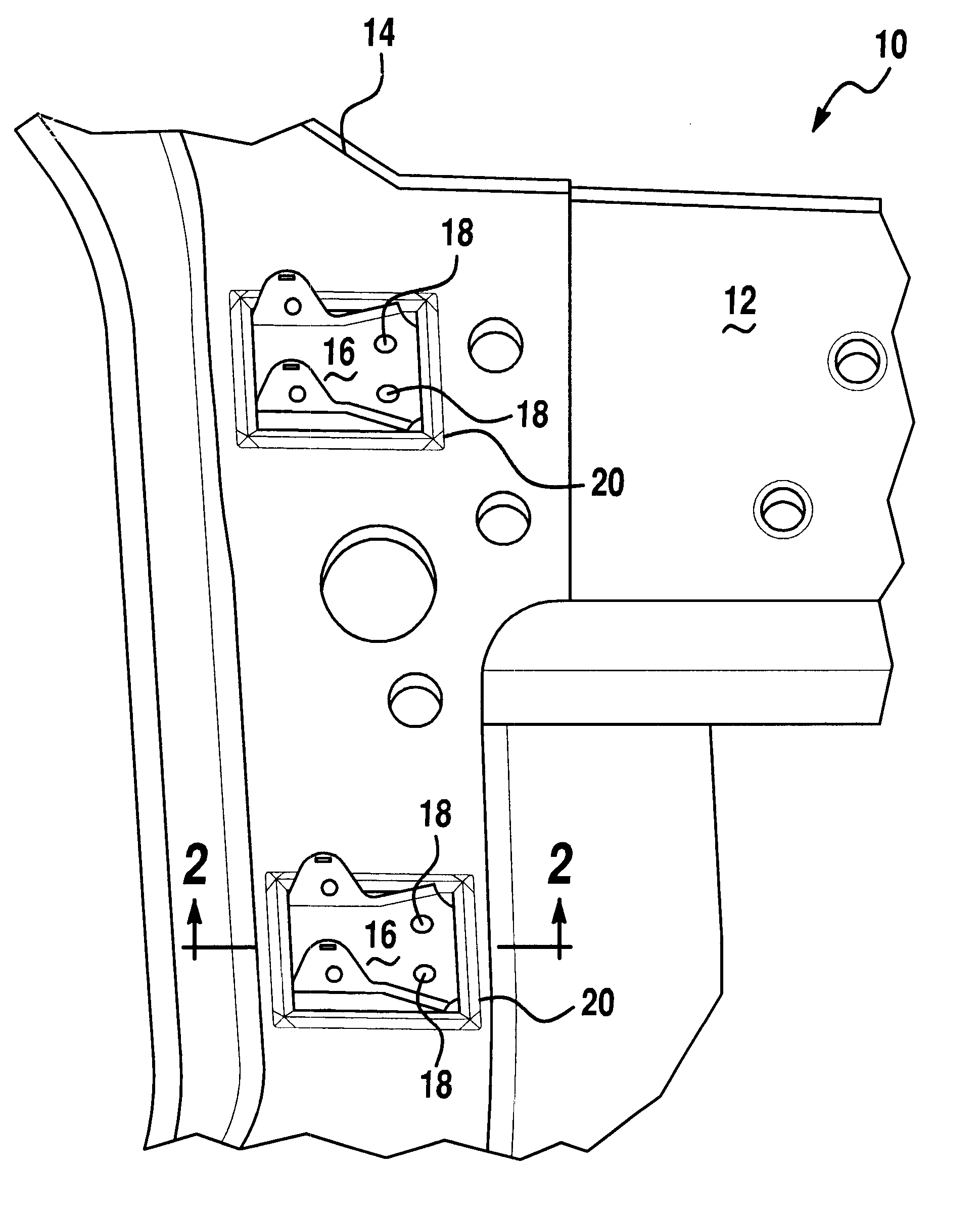
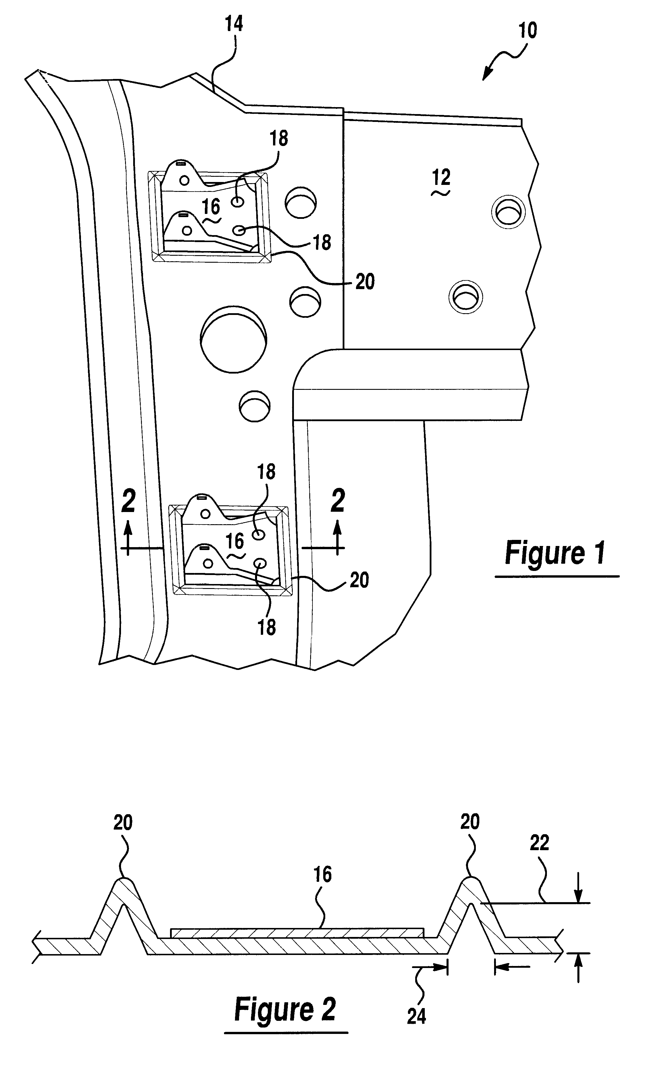
Referring now to FIGS. 1 and 2, there is shown a mounting structure, pillar or member 10 which is made in accordance with the teachings of the preferred embodiment of the invention. As shown best in FIG. 1, mounting structure 10 comprises a member or portion 14 of a conventional vehicle body 12, and may be used or employed in one non-limiting embodiment as an "A-Pillar" of vehicle body 12 on which a vehicle door (not shown) is selectively, conventionally, and operatively mounted. While the following discussion relates to the use of structure 10 as a "pillar" of vehicle body 12 on which a door is selectively mounted, it should be appreciated that structure 10 may be used in other applications to support various other objects or components and / or may be used in combination with other portions of a vehicle or virtually any other type of structure to which objects or components are selectively and desirably attached.

Structure 10 comprises a pillar or member 14 which is selectively and f...


PUM


Abstract

A mounting structure 10 having improved stiffness characteristics. The mounting structure 10 includes a pillar 14 which forms a portion of a vehicle body 12 and which operatively supports a vehicle door which is selectively attached to the pillar 14 by hinges 16. The structure 10 includes a pair of "closed-loop" beads which are formed around hinges 16, and which increase the stiffness characteristics of the pillar 14 and of the vehicle door.

Description

(1) FIELD OF THE INVENTIONThis invention relates to a mounting structure with improved stiffness characteristics, and more particularly, to a structure on which a component, such as a vehicle door, may be selectively mounted and a method for increasing the stiffness of the structure.(2) BACKGROUND OF THE INVENTIONMounting structures are used and / or formed on various assemblies, such as automotive vehicles, to provide support to components which are selectively mounted to the assemblies. For example and without limitation, automotive vehicles include mounting structures or portions of the vehicle body or frame on which components, such as vehicle doors, liftgates or hoods, are typically and selectively mounted.One type of mounting structure, commonly referred to as a "pillar", is a portion of the vehicle frame or body which is used to mount and support a vehicle door. Particularly, a hinge member is typically fixedly and rigidly coupled to the pillar and to the vehicle door, and allo...

Claims


Application Information

Patent Timeline
IPC IPC(8): B62D25/04
CPCB62D25/04E05Y2900/531
Inventor OURCHANE, AMARCHUANG, CHING-HUNGMACHIN, RONALDCRANE, SCOTTWU, XIAO
Owner FORD GLOBAL TECH LLC
Why Eureka
Try Eureka