
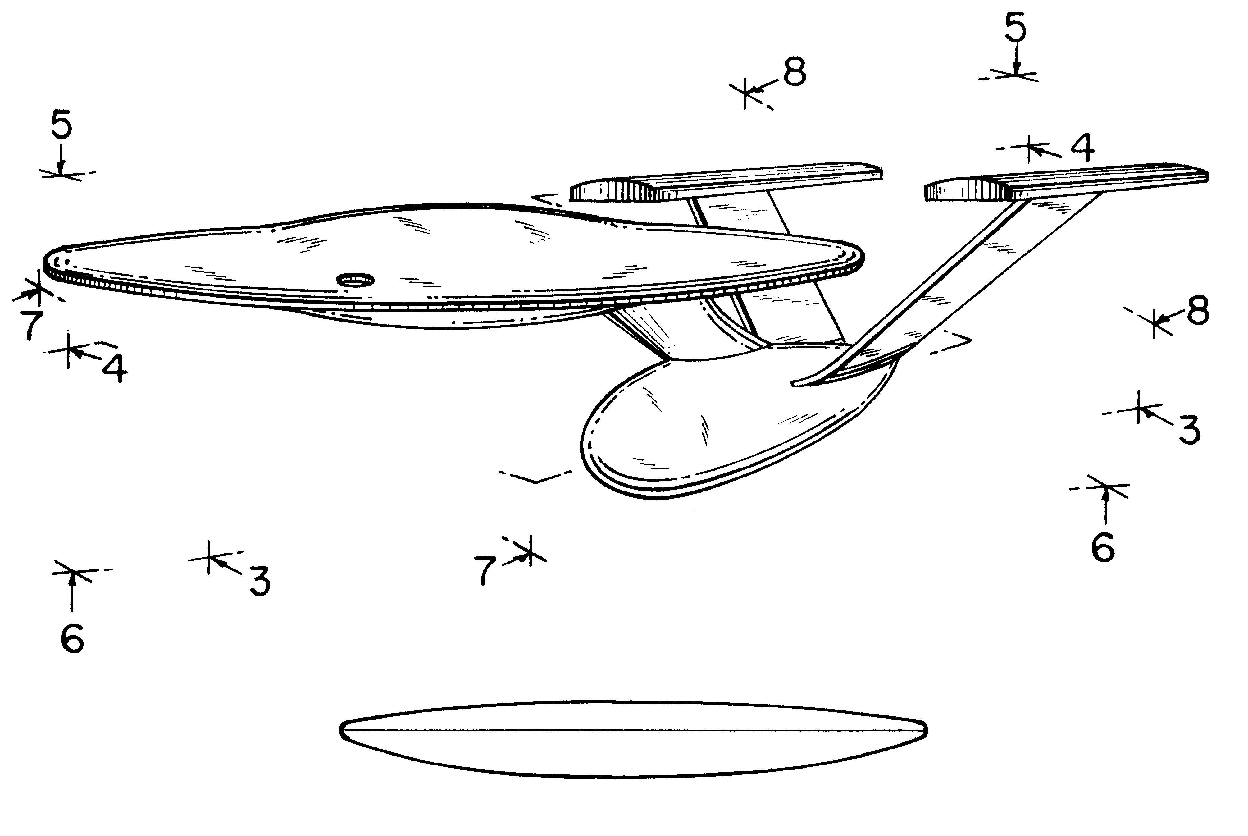
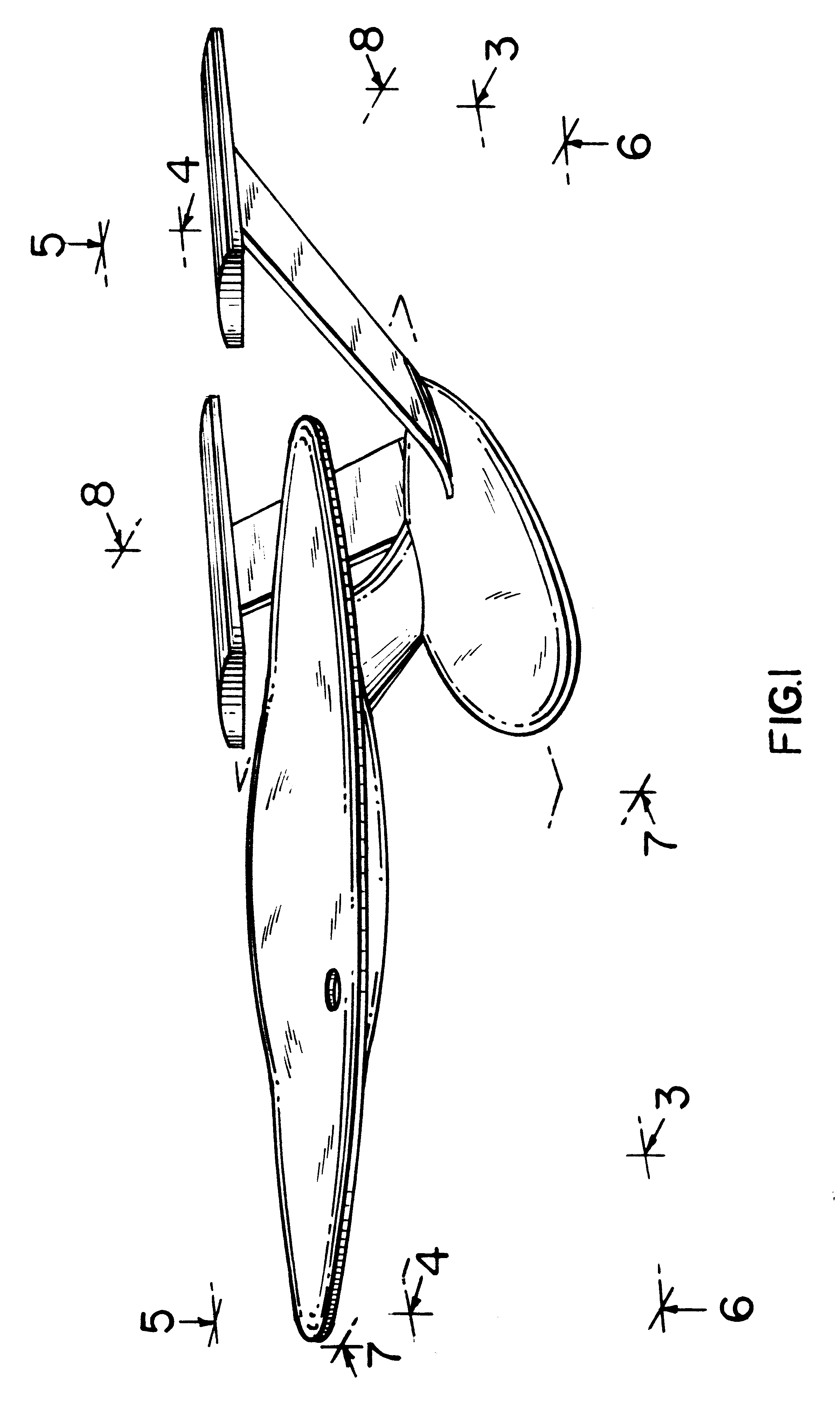
Model space craft glider

a technology for space craft and gliders, applied in toys, toy aircrafts, entertainment, etc., can solve the problems of poor pitch stability, high take off and landing speed, and reduced lift, and achieve the effect of propagating effective stability of the model space cra

Inactive Publication Date: 2002-08-20
LYNN ANTHONY
View PDF9 Cites 16 Cited by
  • Summary
  • Abstract
  • Description
  • Claims
  • Application Information

AI Technical Summary

Benefits of technology

a fixed circular wing means for providing lift, having a topside and an underside and a thickness,
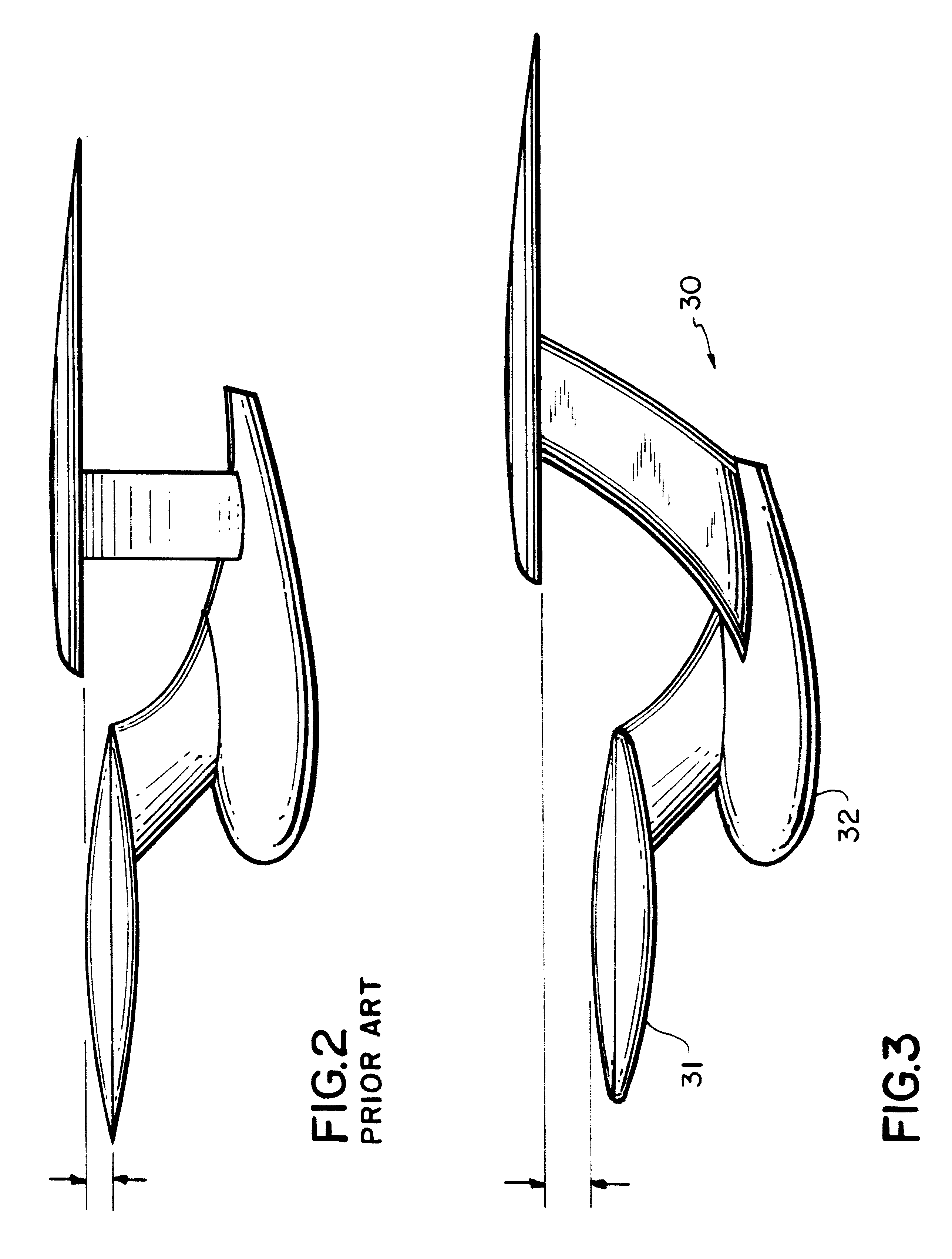
FIGS. 3, 11 and 15 demonstrate the new swept back fin design which advantageously modifies both the structure, in terms of redistribution of forces (See FIG. 11 for the forces indicated by arrows) and f stability, in terms of increasing the side profile area of the fin which will assist the efficiency of flight by acting as larger "rudders."

Problems solved by technology

Further, the thought is, that if the circular wing were fixed and not rotating, it would have such poor pitch stability that the circular wing could only be placed at the rear of the aircraft.
However lift is also reduced, requiring high take off and landing speeds.

Method used


Image

  • Model space craft glider
  • Model space craft glider
  • Model space craft glider

Examples


Embodiment Construction

model U.S.S. Starship Enterprise was constructed which incorporated the changes needed to enable the model space craft to fly efficiently. The model craft constructed was initially based upon the publication disclosure found in publication GB2270478 as depicted in FIGS. 1 to 6 of that publication

There are four modifications made to the model space craft which resulted in the article of the present invention

The airfoil element comprising the circular wing is convex on both sides. The wing of the prior art design followed a typical airfoil section of a typical wing which is less convex on the underside than on the top. The lift that is produced when using this approach is very high and therefore requires a great deal of ballast on the craft to compensate for the lift factor. Firstly, this produces a heavier craft and secondly, it will fly at a higher speed. These two factors will, for all model aircraft, promote a higher mortality rate. It has therefore been necessary to reduce the li...


PUM


Abstract

A model space vehicle having a fixed circular wing, streamlined fuselage, fins with booms attached thereto all efficiently configured to result in an article possessing suitable aerodynamic properties to enable it to glide smoothly through the air for a substantial period of time and substantial distance relative to its size and weight.

Description

1. Field of the InventionThe present invention relates to a model space vehicle configured to possess suitable aerodynamic properties such that it is capable of gliding smoothly through the air for a substantial period of time relative to its size and weight.2. Description of the Prior ArtOver the years conventional aircraft have taken shapes in many forms using fixed wings and tail plane of various platforms. The most commnon wing shapes are rectangular, swept back and delta with varying cross sectional and wing surface areas. Other more recent embodiments include aircraft which have wings which are movable to vary the angle of sweep while others have wings tilting on a horizontal axis to vary the angle of attack.The aircraft wing is modified in a VTOL (vertical take off and landing) and a STOL (short take off and landing) and is generally a function of the propulsion unit used in conjunction with the aircraft.There has been a suggestion that a rotating circular wing can be used ef...

Claims


Application Information

Patent Timeline
Patent Type & Authority Patents(United States)
IPC IPC(8): A63H27/00
CPCA63H27/00
Inventor LYNN, ANTHONY
Owner LYNN ANTHONY
Learn More