
Pivoting injector arrangement

a technology of injectors and slant wells, which is applied in the direction of fluid removal, drilling accessories, borehole/well accessories, etc., can solve the problems of affecting the service life of the injector, the inability of other conventional derricks, particularly those used on mobile carriers, to line up with and service slant wells

Inactive Publication Date: 2002-08-13
NABORS CANADA
View PDF7 Cites 106 Cited by
  • Summary
  • Abstract
  • Description
  • Claims
  • Application Information

AI Technical Summary

Problems solved by technology

In an exceptional case where the range of adjustment of the rig's equipment is insufficient for proper alignment, the rig itself may have to be moved and parked again in a different approach to the well.
Although such manipulation provides an advantageous three dimensional ("3-D") maneuvering capability to the injector, the procedure is somewhat cumbersome and time consuming.
Other conventional derricks, particularly those used on mobile carriers, are more restricted in their ability to line up with and service slant wells.

Method used


Image

  • Pivoting injector arrangement
  • Pivoting injector arrangement

Examples


Embodiment Construction

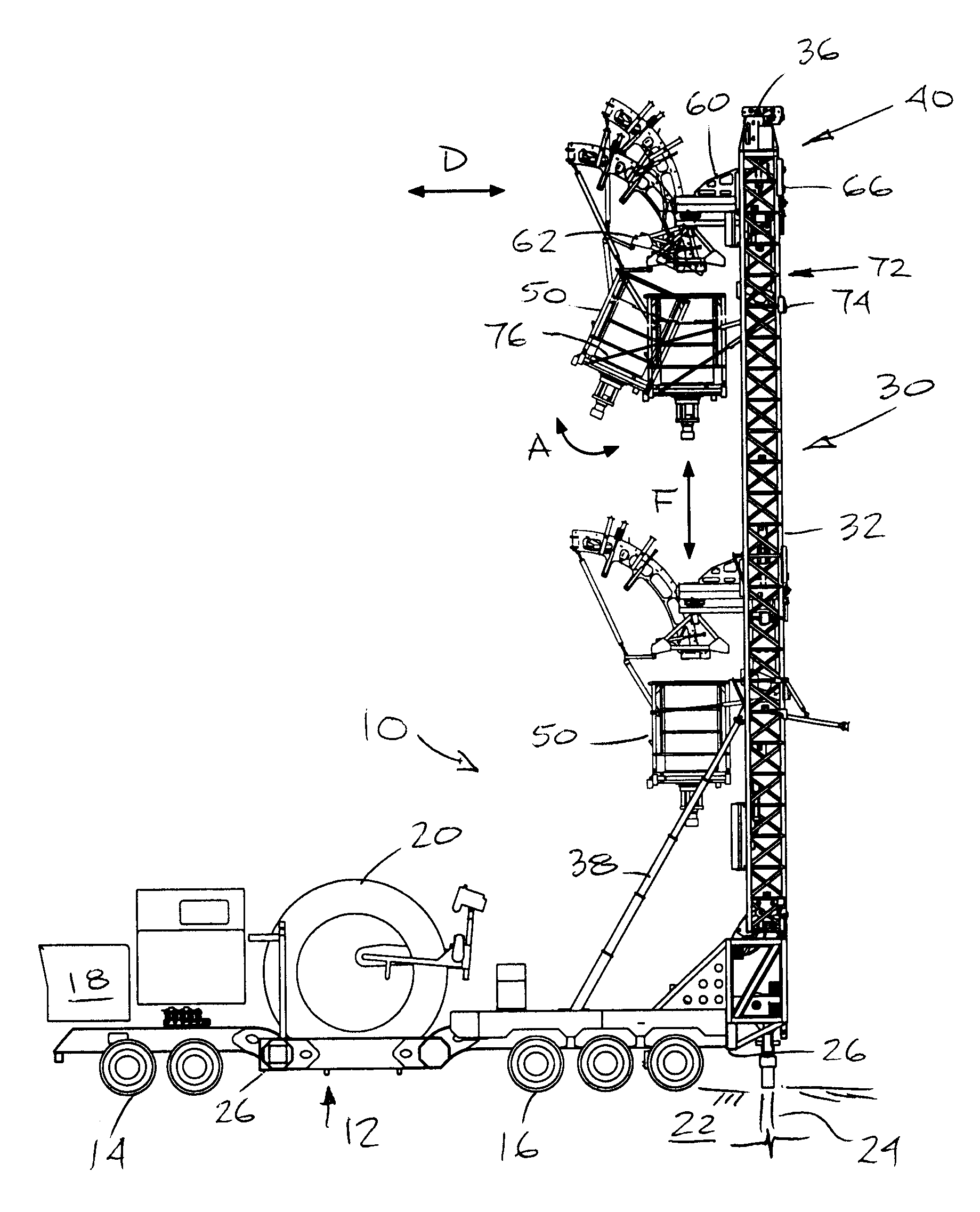
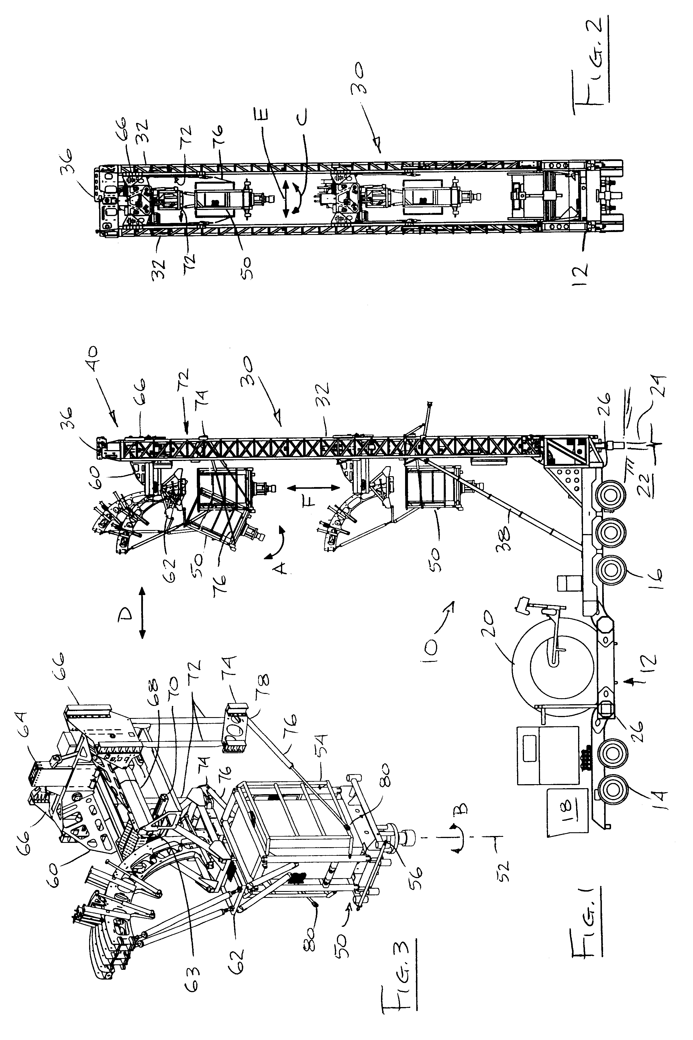
FIG. 1 shows a mobile rig 10 for transporting drilling and servicing equipment to an oil or gas well site. The equipment, such as a cartridge assembly 20 capable of holding various sizes of continuous or coiled tubing ("CT") reels, is located aboard a self-propelled carrier 12 having a tandem axle front end 14 and a triple axle rear end 16. A cab 18 houses an engine for driving the front and / or rear axles, and incorporates conventional controls for steering the carrier over a ground surface 22 and for locating the carrier's rear end over a well. The term "well" is understood herein to mean either an oil or gas well to be drilled, or an existing well or wellhead 24 which is to be tested or serviced. The carrier 12 incorporates a number of hydraulically operated stabilizers 26 for lifting the carrier off the ground and enhancing lateral stability during well operations. The front and rear axle designs may vary depending on the anticipated weight of equipment to be carried and the type...


PUM


Abstract

An injector arrangement for use in a rig has a movable carrier, a derrick tiltably mounted to the carrier, and a trolley capable of sliding along the derrick. An injector cradle is movable along the trolley in at least a plane perpendicular to the derrick and is pivotally mounted beneath the trolley. An injector is supported at its upper end from the cradle. At least two hydraulic cylinders are supported at one end by the derrick and are engaged at an opposed end to a lower end of the injector for rotating and tilting the injector relative to the trolley and derrick.

Description

The present invention relates to drilling and servicing equipment for oil and gas wells generally, and in particular relates to an arrangement for multi-dimensional pivoting of an injector for use in rigs which transport and / or operate equipment for continuous coiled tubing drilling, for conventional joined pipe handling and drilling, and / or for wireline applications.Applicant's U.S. Pat. No. 6,003,598 and corresponding Canadian Patent 2,235,555 for a "Mobile Multi-Function Rig" disclose an injector carried by a cradle which is movable in two planes, namely in both generally vertical and horizontal planes, when the derrick is in an upright operating mode. Such movement helps align an injector over a wellhead. Should the wellbore be inclined, such as in a "slant well", then the orientation of the injector must be further adjusted by slanting the derrick accordingly in one vertical plane and, if need be, the rig's chassis stabilizers can be manipulated somewhat to provide tilt in a se...

Claims


Application Information

Patent Timeline
IPC IPC(8): E21B19/00E21B19/22E21B33/03E21B33/068
CPCE21B19/22E21B33/068
Inventor ANDREYCHUK, MARK T.
Owner NABORS CANADA
Learn More