Locking device with a key-activated cylinder core

a technology of key-activated cylinders and locking devices, which is applied in the direction of cylinder locks, building locks, constructions, etc., can solve the problems of large axial construction length, cumbersome and time-consuming mounting of these components,

Inactive Publication Date: 2002-07-30
HUF HULSBECK & FURST GMBH & CO KG
View PDF6 Cites 11 Cited by
  • Summary
  • Abstract
  • Description
  • Claims
  • Application Information

AI Technical Summary

Problems solved by technology

Mounting of these components is cumbersome and time-consuming.
The disa

Method used


Image

  • Locking device with a key-activated cylinder core
  • Locking device with a key-activated cylinder core
  • Locking device with a key-activated cylinder core

Examples


Embodiment Construction

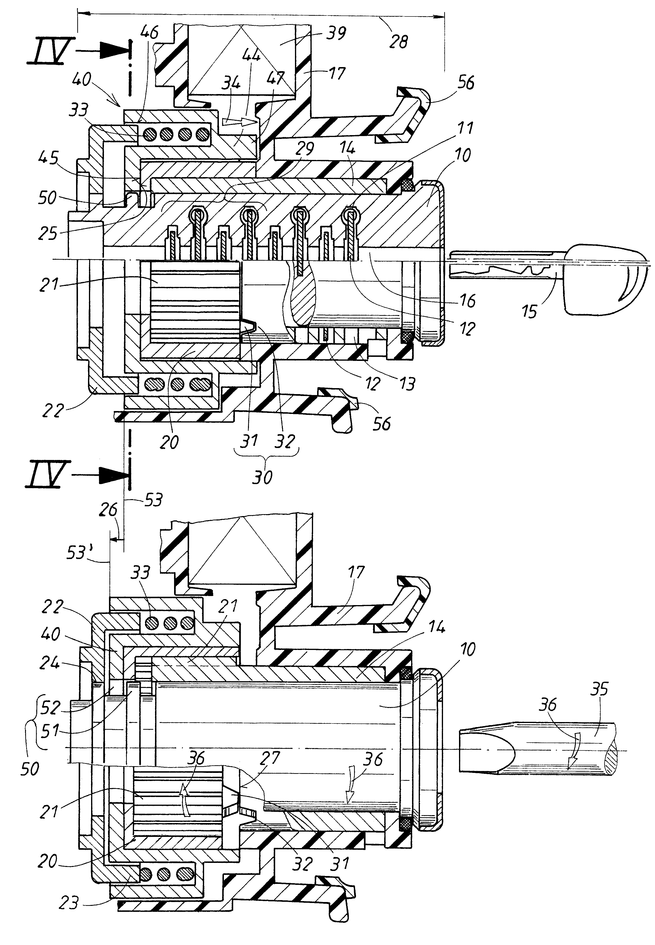
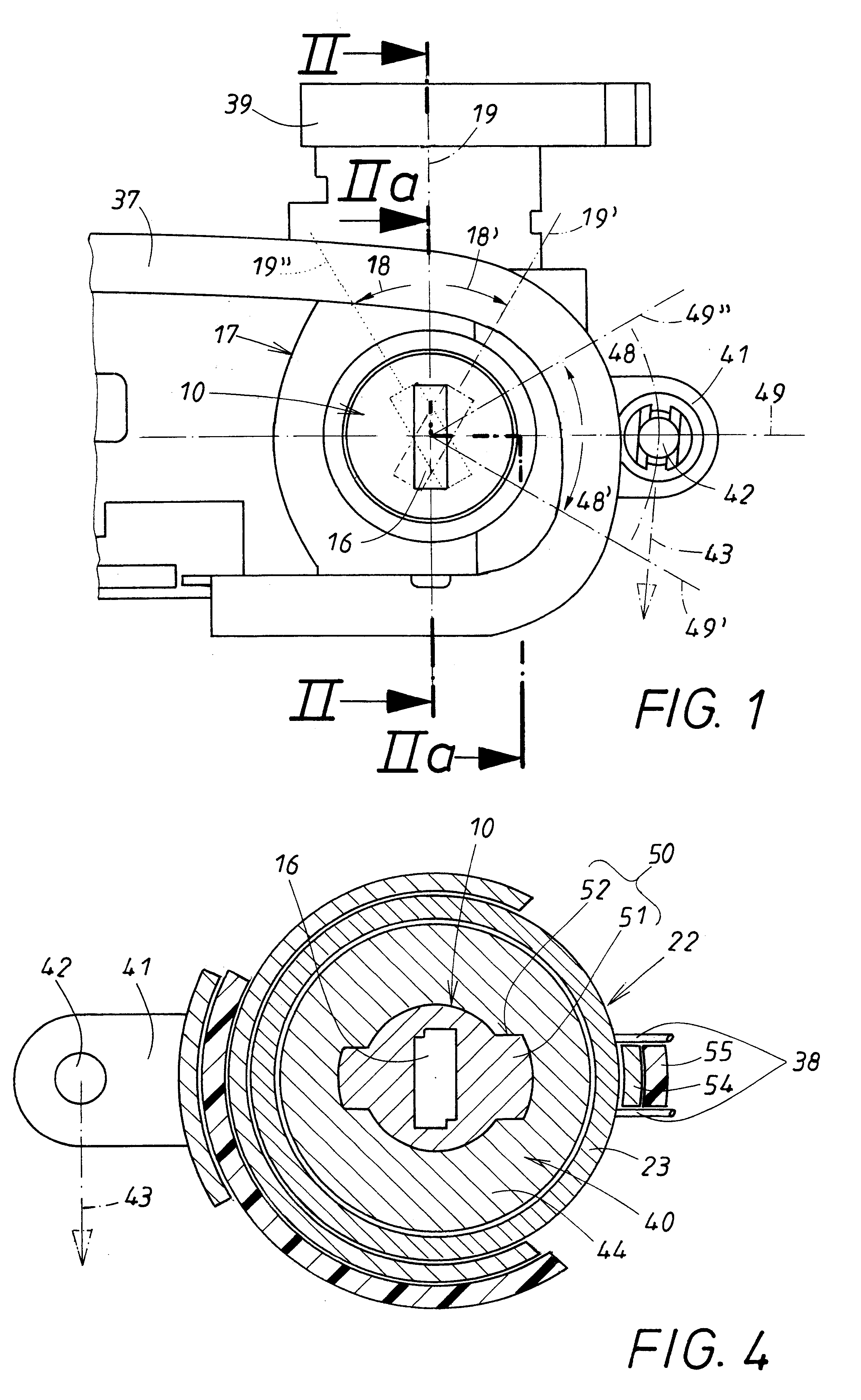
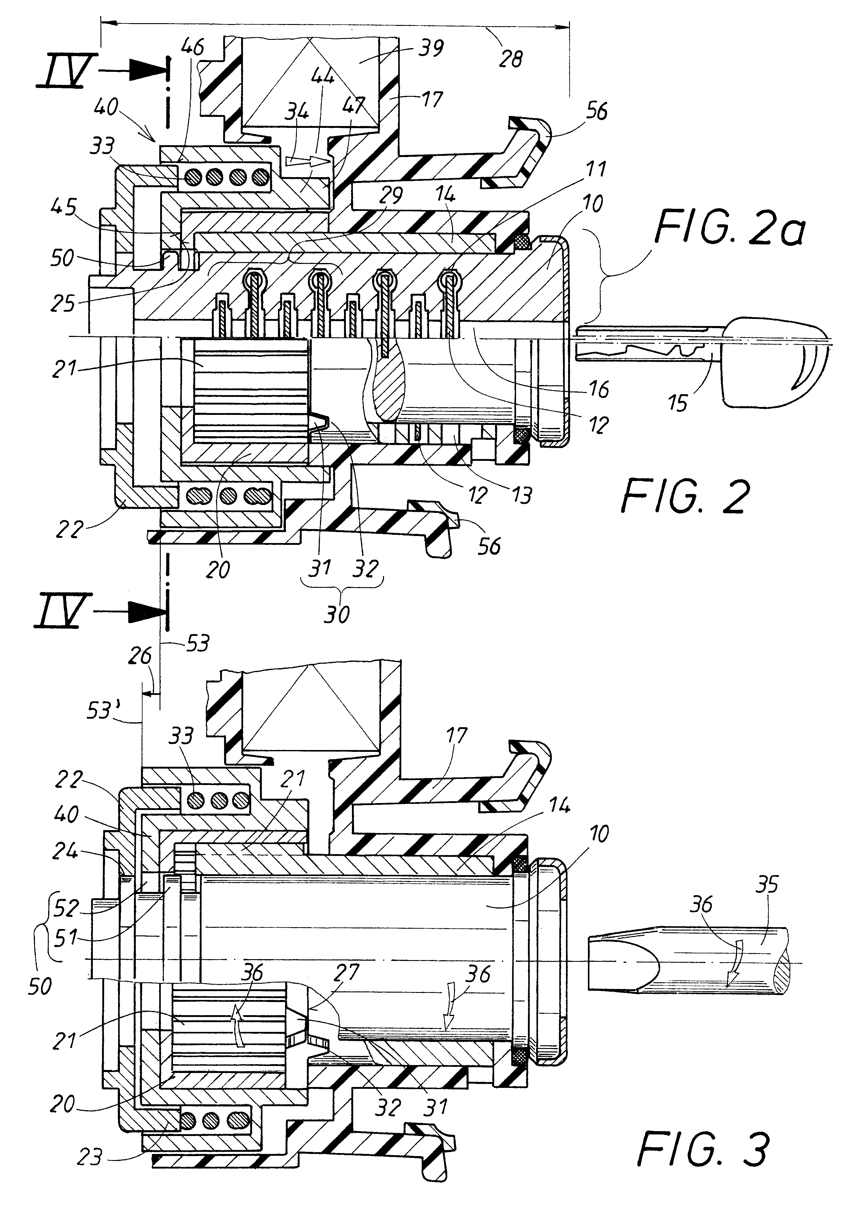
The locking device comprises a cylinder core 10 with tumblers 12 force-loaded by springs 11 and received radially movably in the cylinder core 10 so as to engage normally with their ends stopping points 13 of a cylinder guide 14. The stopping points 13 of neighboring tumblers 12 in the present case are separated from one another by stays in the cylinder guide 14 which increases stability. A key 15 with matched key profile is correlated with the cylinder core 10 which, when inserted, sorts the projecting ends of the tumblers 12 in the key channel 16 of the cylinder core 10 with respect to the core cross-section and thus releases the cylinder core 10 relative to the cylinder guide 14 for rotation.

The cylinder guide 14 serves normally as a rotational support for the cylinder core 10.

The cylinder guide 14 is axially fixedly but rotatably received in the housing 17 which is fastened stationarily within the interior of the motor vehicle door. By means of an overload protection device 30, ...


PUM


Abstract

A locking device with a key-actuated cylinder core has a cylinder guide rotationally supporting the cylinder core and stopping points for tumblers. One area of the cylinder guide is received axially fixed but rotatably in a housing, while the other area is surrounded by a sliding member non-rotatably but axially slidably supported on the cylinder guide. A turning member surrounds the sliding member and is rotatable relative to and synchronously axially movable with the sliding member. A spring acts axially on the turning member. An overload protection device has a control element arranged on the housing and a counter control element, arranged on the sliding member and spring-loaded against the control element, for axially moving the sliding and turning members in an overload situation to release an axial coupling having one coupling member fixedly connected to the cylinder core and another coupling member arranged on the turning member.

Description

1. Field of the InventionThe invention relates to a locking device, in particular, in a motor vehicle, with a key-activated cylinder core which performs locking functions upon rotation. For a rotational support of the cylinder core a cylinder guide is provided having stopping points for tumblers positioned within the cylinder core. In order to make the locking device theft-proof, an overload protection device is provided which is comprised of, on the one hand, an axially fixed profiled control element and a profiled counter control element that is axially movable and spring-loaded against the profiled control element. An overload situation occurs when, without key, a forced rotation is exerted on the cylinder core. In this case, the profiled counter control element is axially lifted off the profiled control element and decouples a turning member relative to the cylinder core, and the cylinder guide is freely rotatable relative to the cylinder core because the cylinder core is fixedl...

Claims


Application Information

Patent Timeline
IPC IPC(8): E05B17/04E05B17/00E05B15/00E05B17/20E05B29/10
CPCE05B17/0058E05B17/04Y10T70/7949
Inventor GEURDEN, ARMIN
Owner HUF HULSBECK & FURST GMBH & CO KG
Why Eureka
Try Eureka