Eureka AIR delivers breakthrough ideas for toughest innovation challenges, trusted by R&D personnel around the world.

Method for coding an audio signal

Inactive Publication Date: 2002-07-23
FRAUNHOFER GESELLSCHAFT ZUR FOERDERUNG DER ANGEWANDTEN FORSCHUNG EV
View PDF11 Cites 260 Cited by
  • Summary
  • Abstract
  • Description
  • Claims
  • Application Information

AI Technical Summary

Problems solved by technology

This signal obviously constitutes a problem for the afore-mention traditional methods, such as e.g. transformation coding or coding of spectral data or linear prediction coding of the time range data.
In case of noise-like signals, the human hearing system is not capable of ascertaining the exact path in time of such a signal.
However, this constitutes are relatively coarse system of noise detection.
However, this method of detection is suitable only for strictly stationary signals.
It does not permit a detection of situations in which sinusoidal signals with slightly varying frequencies in relation to time are present.
A major problem in this respect is the limited dynamic range of the predictor.
A noise-like frequency group of high level dominates the predictor due to the resulting high error.
The initially described standard MPEG-2 Advanced Audio Coding (AAC) does not support the possibility of noise substitution.
The considerable data rate savings are thus not possible so far with the presently existing standard.
The known noise substitution method involves the problem that parts of the input signal can be substituted by noise and then can be decoded again with inaudible quality losses when the input signal exhibits a uniform noise structure, i.e. a plane or flat spectrum.
This does not hold in case of transient signals or voice signals, so that either the use of noise substitution has to be dispensed with completely or, in case noise substitution is employed nevertheless, disturbing distortions of the signal are caused.

Method used


Image

  • Method for coding an audio signal
  • Method for coding an audio signal
  • Method for coding an audio signal

Examples


Embodiment Construction

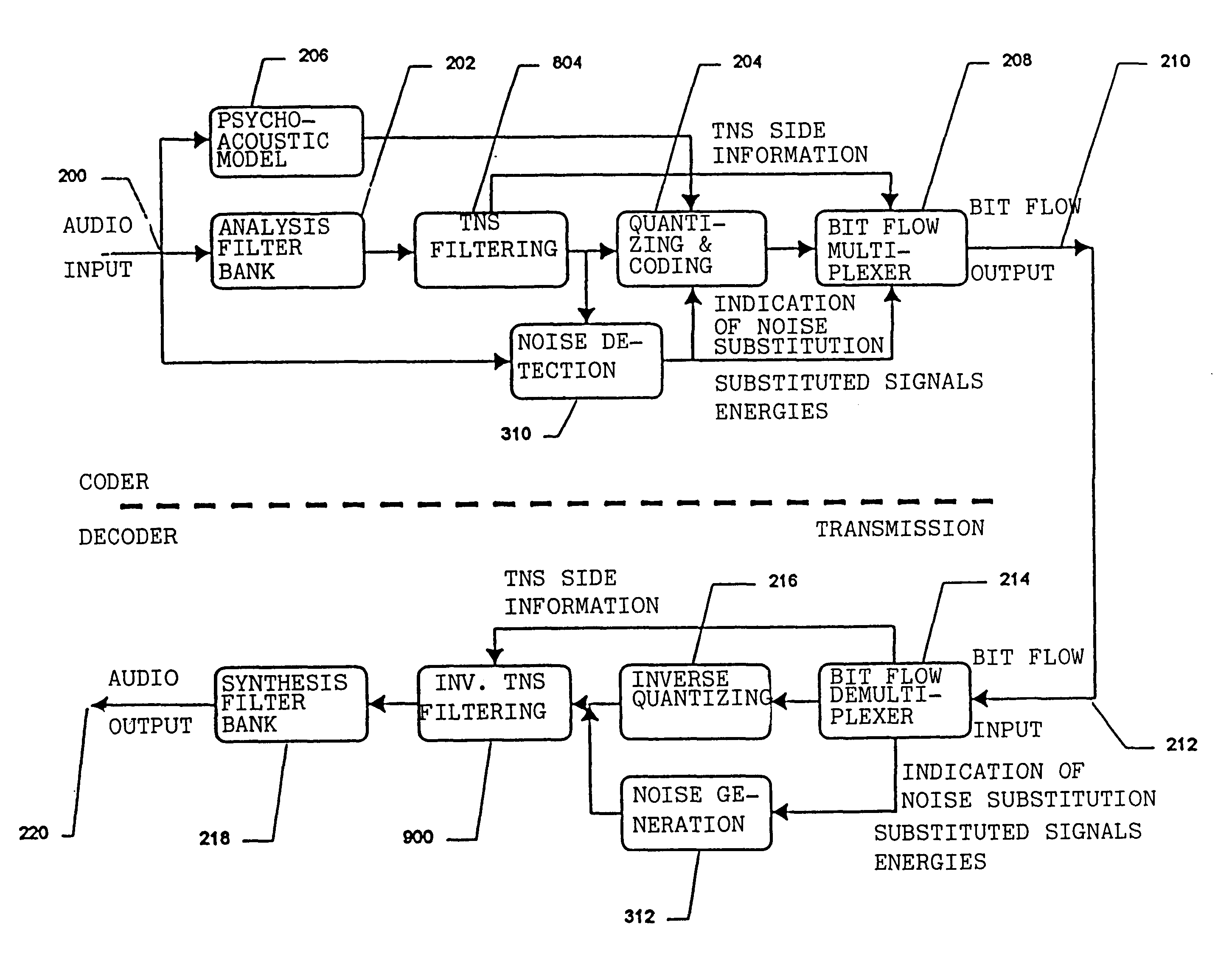
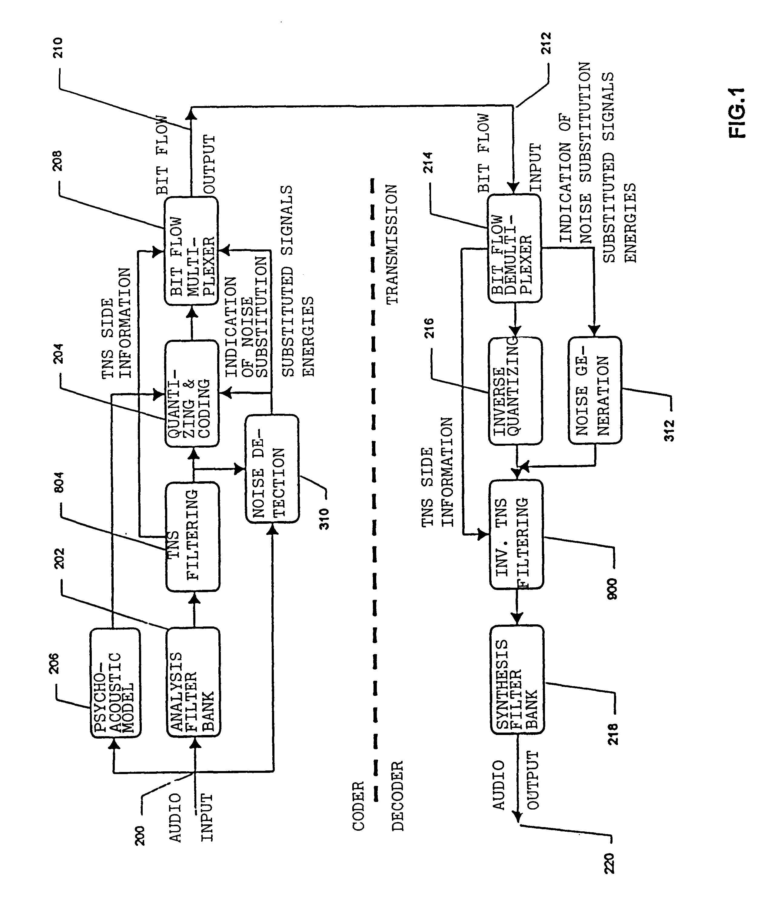
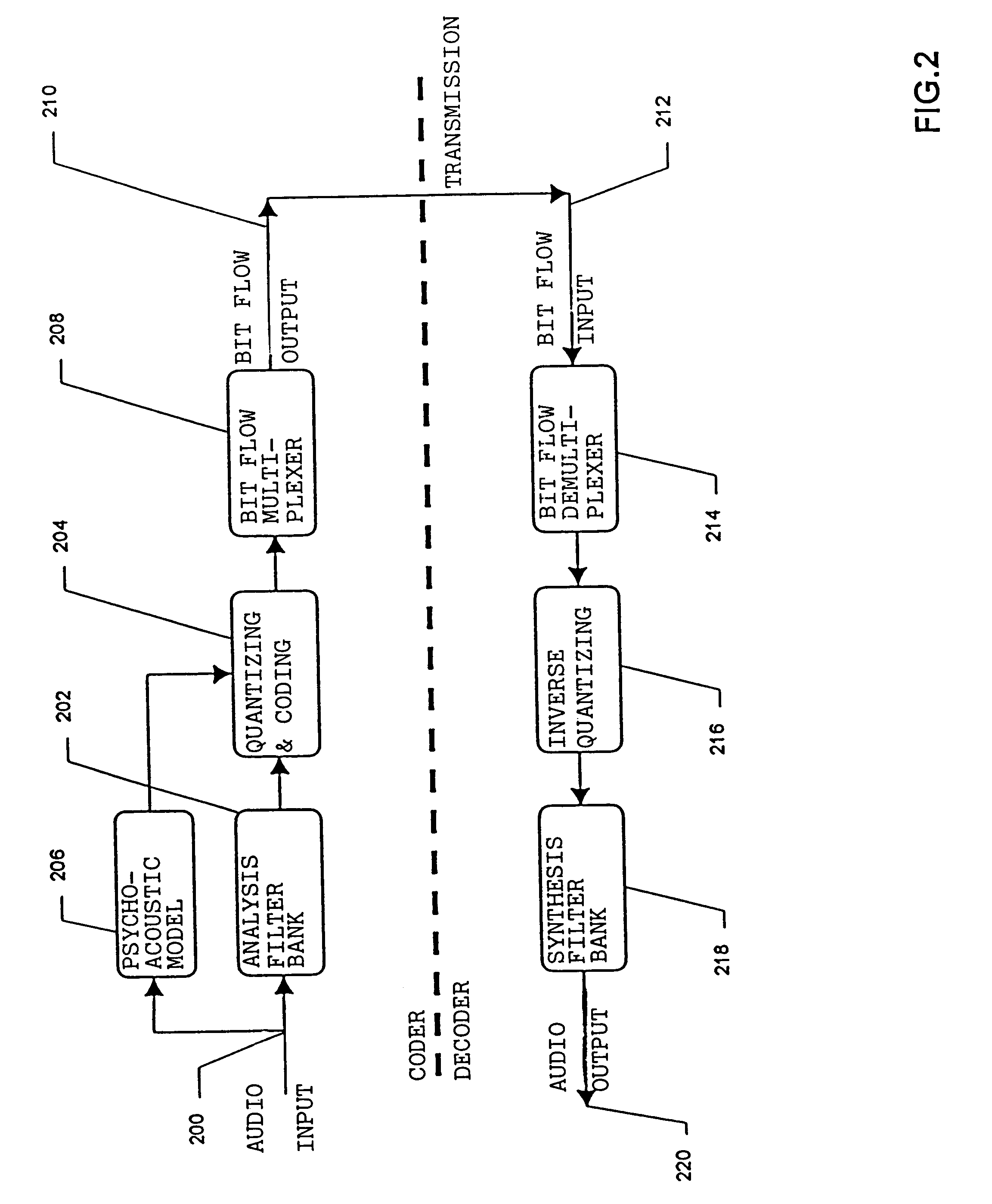
FIG. 1 shows a coder and a decoder according to the present invention. In comparison with the coder described in FIG. 3, the coder according to the invention, as shown in FIG. 1, contains a combination of TNS filtering and noise substitution. In contrast to the known coder, which performs noise substitution of spectral values, the coder shown in FIG. 1 additionally carries out noise substitution of the spectral residual values at the output of TNS filter 804. In groups of spectral residual values or scale factor bands with spectral residual values, the noise substitution ascertains a measure of the energy of the spectral residual values in a group or in a scale f actor band, and a noise substitution indication to quantizer and coder 204 as well as to bit flow multiplexer 208 is carried out analogously with noise substitution for original spectral values.

In the decoder, the opposite, analogous process takes place. Bit flow demultiplexer 214 supplies TNS side information to the invers...


PUM


Abstract

A method for coding or decoding an audio signal combines the advantages of TNS processing and noise substitution. A time-discrete audio signal is initially transformed to the frequency domain in order to obtain spectral values of the temporal audio signal. Subsequently, a prediction of the spectral values in relation to frequency is carried out in order to obtain spectral residual values. Within the spectral residual values, areas are detected encompassing spectral residual values with noise properties. The spectral residual values in the noise areas are noise-substituted, whereupon information concerning the noise areas and noise substitution is incorporated into side information pertaining to a coded audio signal. Thus, considerable bit savings in case of transient signals can be achieved.

Description

The present invention relates to a method for coding audio signals, and in particular to a method for coding an audio signal for the standard MPEG-2 AAC being just developed.BACKGROUND OF THE INVENTION AND PRIOR ARTThe standardization organization ISO / IEC JTC1 / SC29 / WG11, which is also known as Moving Pictures Expert Group (MPEG), was founded in 1988 in order to specify digital video and audio coding schemes for low data rates. The first specification phase was completed in November 1992 by the standard MPEG-1. The audio coding system according to MPEG-1, which is specified in ISO 11172-3, operates in a single-channel or two-channel stereo mode at sampling frequencies of 32 kHz, 44.1 kHz and 48 kHz. The standard MPEG-1 Layer II delivers broadcasting quality, as specified by the International Telecommunication Union, at a data rate of 128 kb / s per channel.In its second development phase, the aims of MPEG consisted in defining multi-channel extension for MPEG-1-Audio, which was suppose...

Claims


Application Information

Patent Timeline
IPC IPC(8): H04B1/66G10L19/028H03M7/30
CPCG10L19/028H04B1/665H04B1/66
Inventor HERRE, JURGENGBUR, UWEEHRET, ANDREASDIETZ, MARTINTEICHMANN, BODOKUNZ, OLIVERBRANDENBURG, KARLHEINZGERHAUSER, HEINZ
Owner FRAUNHOFER GESELLSCHAFT ZUR FOERDERUNG DER ANGEWANDTEN FORSCHUNG EV
Why Eureka
Eureka Blog
Learn More