Locomotive brake valve handle with wear pad

a technology of brake valve handle and wear pad, which is applied in the direction of mechanical control device, process and machine control, instruments, etc., can solve the problem of wear of hardened metal of the handl

Inactive Publication Date: 2002-06-25
WESTINGHOUSE AIR BRAKE TECH CORP +1
View PDF7 Cites 2 Cited by
  • Summary
  • Abstract
  • Description
  • Claims
  • Application Information

AI Technical Summary

Benefits of technology

It is, therefore, one of the primary objects of the present invention to provide a brake handle with a wear pad which can be replaced when it is worn rather than replace the entire handle.
It is also an object of the present invention to provide an a wear pad for a brake handle that is easily replaced.
An additional object of the present invention is to provide a wear pad for a handle that can be used with existing handles that have worn.

Problems solved by technology

However, the handle comes into physical contact with the brake valve assembly as it is moved through the application zone causing the hardened metal of the handle to wear where it interfaces with the valve.

Method used


Image

  • Locomotive brake valve handle with wear pad
  • Locomotive brake valve handle with wear pad
  • Locomotive brake valve handle with wear pad

Examples


Embodiment Construction

Prior to proceeding with the more detailed description of the present invention it should be noted that, for the sake of clarity, identical components which have identical functions have been designated by identical reference numerals throughout the several views illustrated in the drawings.

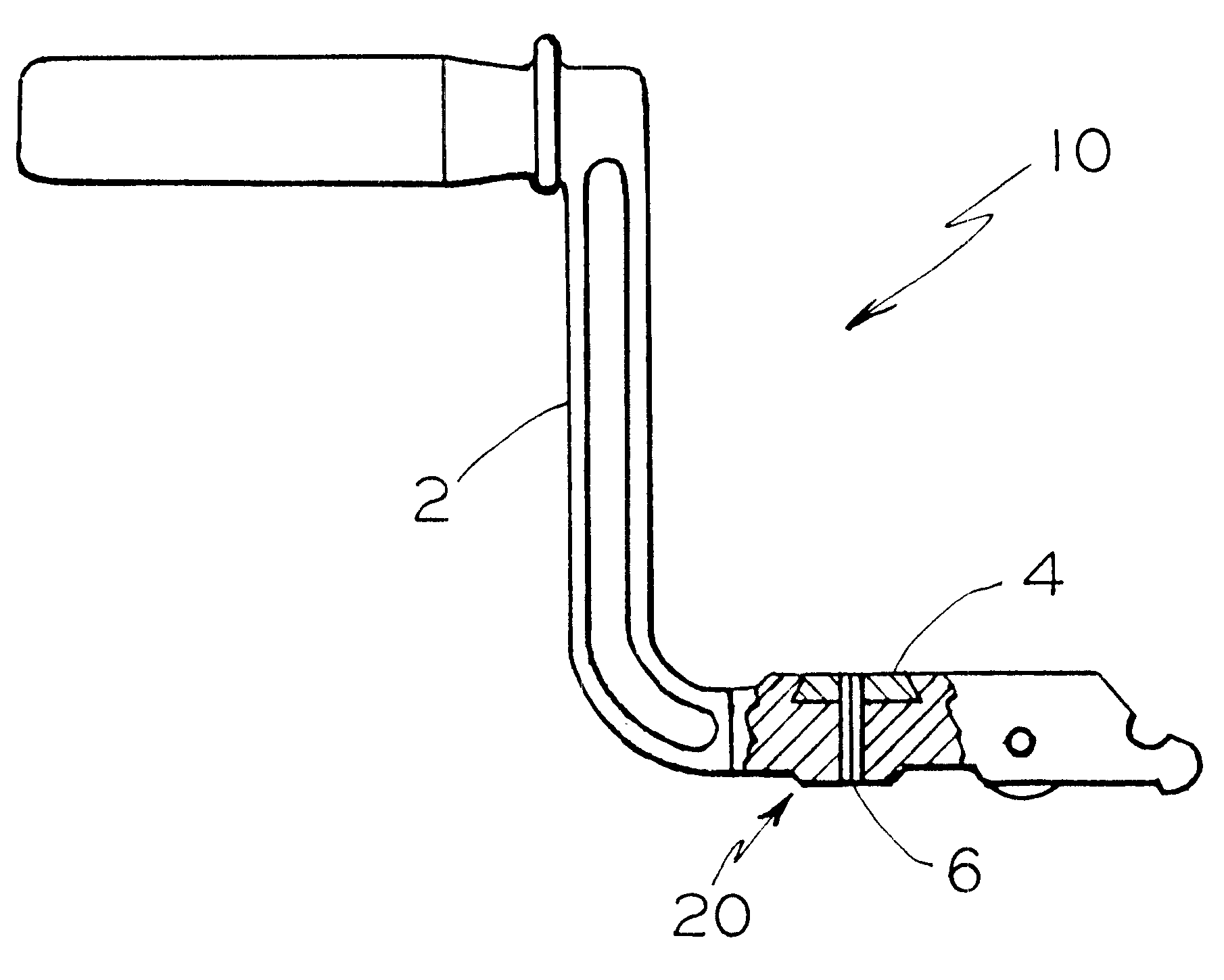
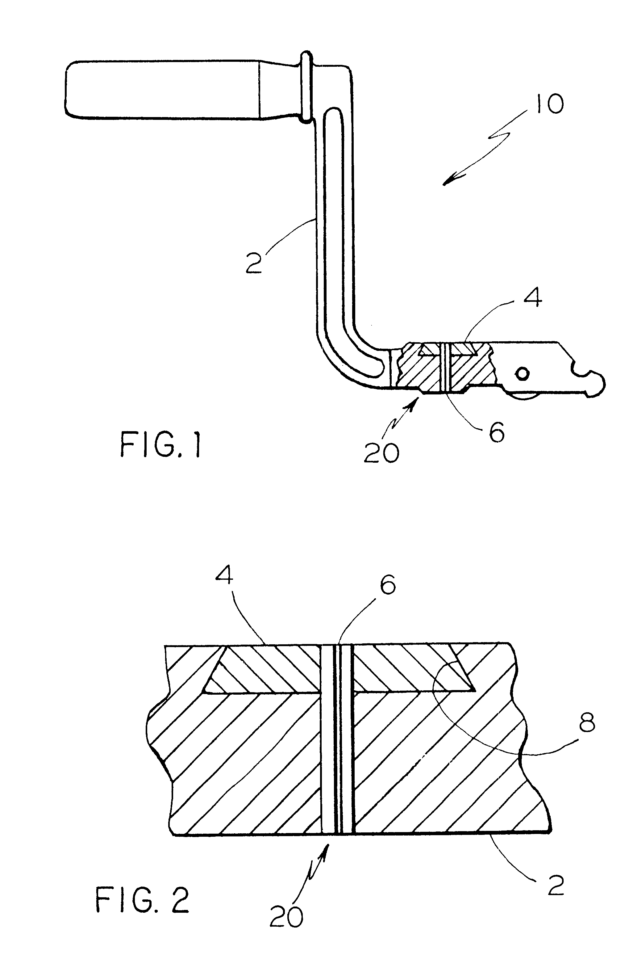
Illustrated in FIGS. 1 and 2 is a locomotive brake valve handle assembly, generally designated 10, incorporating an embodiment of the present invention. The present invention provides such brake valve handle assembly 10 for use in a locomotive brake valve (not shown) of a railway braking system.

The handle assembly 10 includes a handle 2 for manually adjusting such brake valve to various positions. There is a cavity 8 formed in such handle 2 having a predetermined shape and a predetermined width. Such cavity 8 is at least adjacent a top surface of the handle 2 that is disposed adjacent a slot in a housing of such brake valve. Such cavity 8 extends across the diameter of the handle 2 and such prede...


PUM


Abstract

The present invention provides a brake valve handle assembly for use in a brake valve of a railway braking system. The handle assembly comprises a handle for manually adjusting such brake valve to various positions and having a cavity with a predetermined shape and a predetermined width formed in the handle at least adjacent a top surface thereof that is disposed adjacent a slot formed in a housing of such brake valve. The handle assembly further includes a wear pad mounted in the cavity of the handle and a means for securing the wear pad to the handle.

Description

The present invention relates, in general, to a handle for an independent brake valve, and more particularly, the present invention relates to a brake handle which has incorporated a wear pad into the handle in the area of the handle that comes in contact with such brake valve.Independent manually operated brake valves have been used in the railroad industry for many years and provide a means for independent control of the locomotive brake cylinder pressure irrespective of the automatic brake. The independent brake valve has two positions. There is a Release position at one end of the quadrant and a Full Application position at the other end of the quadrant. From Release to Full Application position is an application zone or sector and the further the handle is moved to the right into the sector, the greater will be the application pressure available until full application pressure is obtained at the extreme right of the handle movement. Movement of the independent brake valve handl...

Claims


Application Information

Patent Timeline
Patent Type & Authority Patents(United States)
IPC IPC(8): G05G1/08G05G1/00
CPCG05G1/08Y10T74/20744
Inventor MITSCH, MATTHEW D.
Owner WESTINGHOUSE AIR BRAKE TECH CORP
Why Eureka
Try Eureka