
Shock-absorbent snowplow mount

a technology of shock absorption and snowplow, which is applied in the direction of snow cleaning, way cleaning, construction, etc., to achieve the effect of promoting wear and avoiding shock

Inactive Publication Date: 2002-06-25
BURKE TRUCK & EQUIP
View PDF7 Cites 48 Cited by
  • Summary
  • Abstract
  • Description
  • Claims
  • Application Information

AI Technical Summary

Benefits of technology

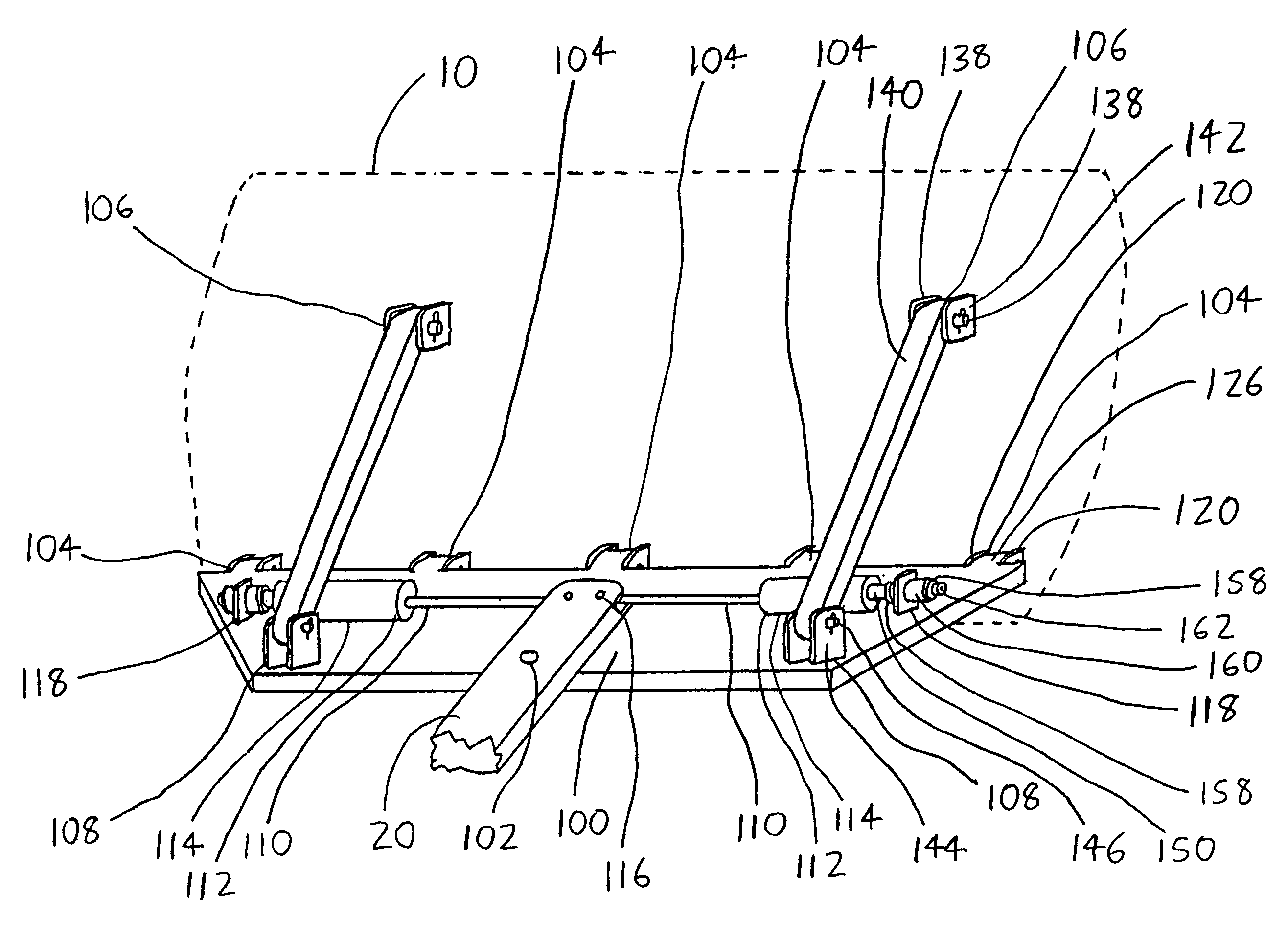
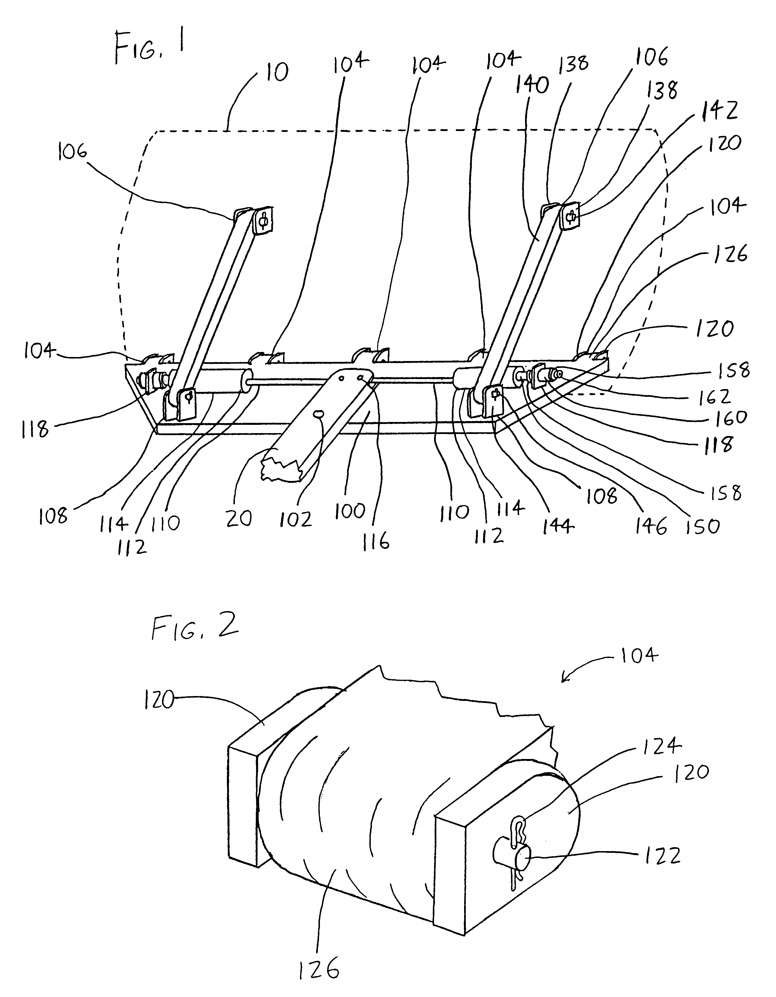
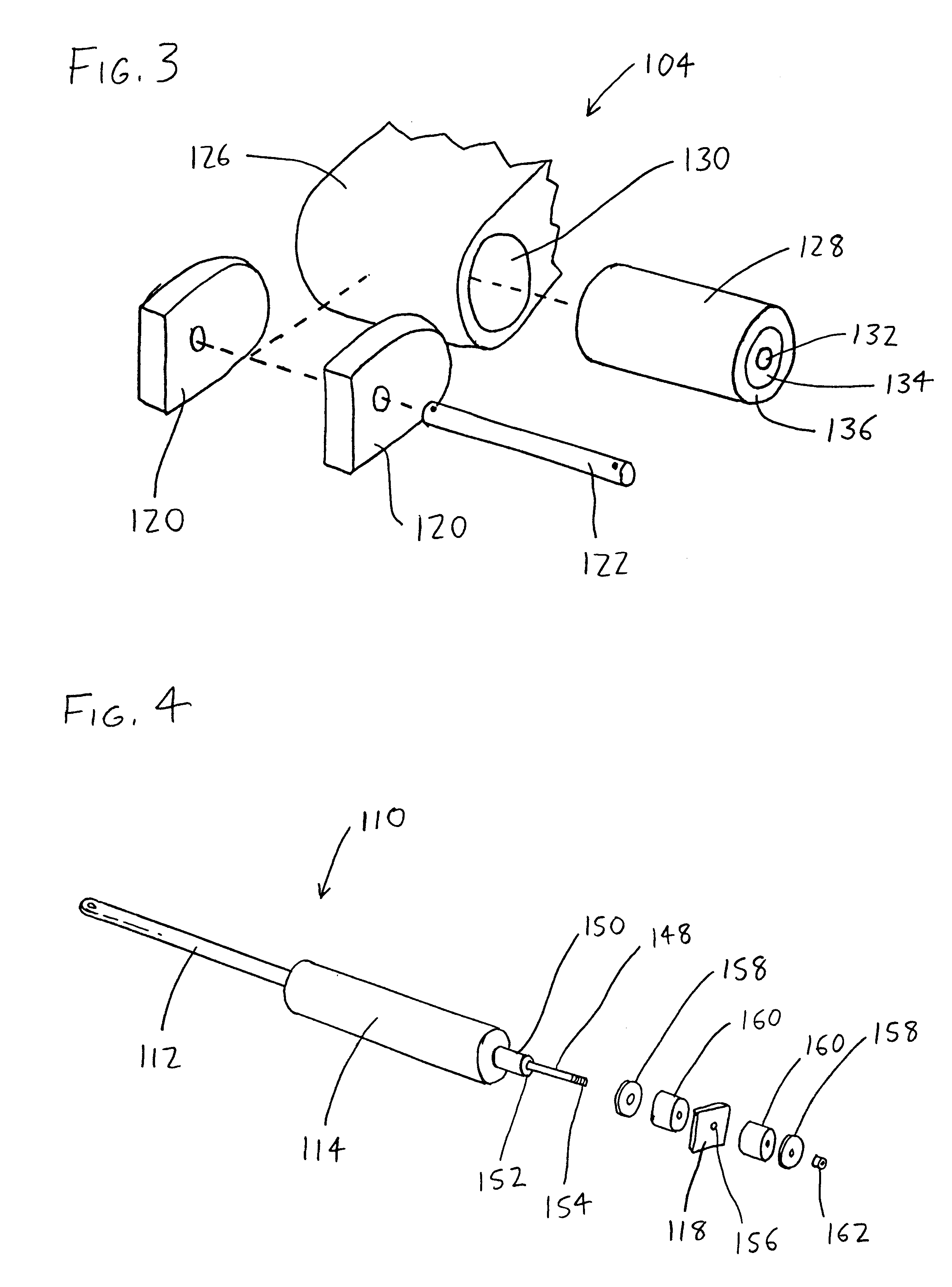
(1) The plow moldboard is affixed to a plow reversing table at one or more pivots which allow the moldboard to be rotatably repositioned with respect to the reversing table. One of the moldboard or the reversing table includes a bearing thereon, with the bearing having a bearing bore defined therein. The other of the moldboard or the reversing table includes a pin which is elastically journalled within the bearing bore so that the pin and bearing may rotate with respect to each other, and additionally translate with respect to each other in radial directions (i.e., in planes which are generally parallel to the axes of the pin and the bearing bore). Therefore, the pin will translate within the bearing when the moldboard is subjected to loading. Such translation will help to delay triggering of any trip edge situated on the moldboard, and will thereby help avoid the shock that occurs from such triggering and allow the pivots to avoid breakage. The elastic journalling may be accomplished by interposing a bushing between the bearing and the pin wherein the bushing is at least partially elastic. The bushing preferably includes a rigid inner sleeve wherein the pin is received, and an elastic outer sleeve wherein the inner sleeve is situated. The inner sleeve and outer sleeve are preferably bonded together so as to prevent the two from separating under loading, which can promote wear between the inner and outer sleeves.

Problems solved by technology

(1) The plow moldboard is affixed to a plow reversing table at one or more pivots which allow the moldboard to be rotatably repositioned with respect to the reversing table. One of the moldboard or the reversing table includes a bearing thereon, with the bearing having a bearing bore defined therein. The other of the moldboard or the reversing table includes a pin which is elastically journalled within the bearing bore so that the pin and bearing may rotate with respect to each other, and additionally translate with respect to each other in radial directions (i.e., in planes which are generally parallel to the axes of the pin and the bearing bore). Therefore, the pin will translate within the bearing when the moldboard is subjected to loading. Such translation will help to delay triggering of any trip edge situated on the moldboard, and will thereby help avoid the shock that occurs from such triggering and allow the pivots to avoid breakage. The elastic journalling may be accomplished by interposing a bushing between the bearing and the pin wherein the bushing is at least partially elastic. The bushing preferably includes a rigid inner sleeve wherein the pin is received, and an elastic outer sleeve wherein the inner sleeve is situated. The inner sleeve and outer sleeve are preferably bonded together so as to prevent the two from separating under loading, which can promote wear between the inner and outer sleeves.
(2) The reversing table is rotatably affixed to the vehicle mount with a linear actuator affixed therebetween so that actuation of the linear actuator will cause the reversing table to rotate with respect to the vehicle mount. The linear actuator is elastically mounted between the reversing table and vehicle mount so that the two may rotate a slight amount with respect to each other (with such rotation being elastically resisted), and so that shock loading of the moldboard (and thus the reversing table) will not be readily transmitted to the linear actuator. The linear actuator is preferably mounted to at least one of the vehicle mount and the reversing table by an actuator anchor wherein an elastic cushion is fit between the linear actuator and actuator anchor. The actuator anchor may have a mounting bore in which the linear actuator is slidably fit, and an elastic cushion may be fit about the linear actuator and closely between the linear actuator and actuator anchor. Then, when the linear actuator translates within the mounting bore of the actuator anchor, the elastic cushion will be compressed or expanded by a corresponding amount.

Method used


Image

  • Shock-absorbent snowplow mount
  • Shock-absorbent snowplow mount
  • Shock-absorbent snowplow mount

Examples


Embodiment Construction

Referring to FIG. 1, an exemplary embodiment of the invention is shown from the rear, i.e., from the front of a plowing vehicle (not shown) and facing forwardly towards the rear of a moldboard 10 (shown in phantom). A portion of a vehicle mount 20 extends forwardly to be pivotally anchored to a reversing table 100 at a table pivot 102. The moldboard 10 is pivotally affixed with respect to the reversing table 100 about a horizontal axis at several pivots which will be referred to herein as base pivots 104, forward upper pivots 106, and rear lower pivots 108. (It is noted that actuators and / or other structures for lifting the moldboard 10 are not shown in the drawings.) These pivots 104 / 106 / 108, being the juncture points between the moldboard 10 and the reversing table 100, are subject to significant wear owing to road vibration and also to shock from impacts between the moldboard 10 and objects in the plowing path. This problem and others are addressed by the pivot arrangement discus...


PUM


Abstract

A snowplow mount is provided wherein a vehicle mount extending from the plowing vehicle is affixed to a reversing table, which is in turn rotatably connected to a plow moldboard at one or more pivots. One of the moldboard or the reversing table includes a bearing thereon, the bearing having a bearing bore defined therein. The other of the moldboard or the reversing table includes a pin which is elastically journalled within the bearing so that the pin and bearing may both rotate with respect to each other as well as translate with respect to each other in radial directions (i.e., in planes which are generally parallel to the axes of the pin and the bearing bore). Thus, loading of the moldboard allows the moldboard to translate with respect to the reversing table at the pivot as well as rotate. The reversing table is rotatably affixed to the vehicle mount with a linear actuator affixed therebetween so that actuation of the linear actuator will cause the reversing table to rotate with respect to the vehicle mount. The linear actuator is elastically mounted between the reversing table and vehicle mount so that the two may rotate a slight amount with respect to each other, with such rotation being elastically resisted. As a result, shock loading of the moldboard (and thus the reversing table) will not be readily transmitted to the linear actuator.

Description

This disclosure concerns an invention relating generally to shock-absorbing devices for snowplows, and more specifically to shock-absorbing devices for assemblies which mount snowplow moldboards to their plowing vehicles.Most moldboards for snowplows are affixed to their plowing vehicles by an assembly which will be referred to herein as a vehicle mount, which may take a variety of forms. Often, the vehicle mount includes a mounting frame which is permanently or removably attached to the plowing vehicle. A support frame, which is often provided as a truss-like structure commonly referred to as an A-frame, bears the moldboard and removably attaches to the mounting frame so that the support frame (and its associated moldboard) can be removed from the vehicle. The moldboard is often pivotally affixed to the support frame (and more generally to the vehicle mount) by an assembly referred to as a reversing table so that the reversing table and moldboard may rotate in one or more degrees o...

Claims


Application Information

Patent Timeline
IPC IPC(8): E01H5/06E01H5/04
CPCE01H5/06
Inventor JONES, DANIEL K.JONES, JAYSON D.
Owner BURKE TRUCK & EQUIP
Learn More