Mold clamping apparatus

a technology of clamping apparatus and clamping chamber, which is applied in the field of mold clamping apparatus, can solve the problems of difficulty in shortening the length of time it takes for the mold to open or close, simultaneous operation of two kinds of cylinders, and abed of operating oil

Inactive Publication Date: 2002-05-28
A K TECH LAB INC
View PDF11 Cites 10 Cited by
  • Summary
  • Abstract
  • Description
  • Claims
  • Application Information

AI Technical Summary

Problems solved by technology

Therefore, it has been difficult to shorten the length of the time it takes for the molds to open, or to close, by simultaneously operating the mold opening / closing cylinder 4 and the differential mold clamping cylinder 6, each of which employs different system.
Thus, even in a mold clamping apparatus of the type which utilizes a differential mold clamping cylinder operative in a differential manner with a small abed of hydraulic oil to open and close a core as well as to clamp molds and utilizes a mold opening / closing cylinder which is of a normal configuration and requires a large abed of hydraulic oil to open and close a movable mold, the simultaneous operation of the two kinds cylinders, which has been difficult until now, is achieved.
An excessive abed of operating oil results due to the fact that there is a difference in volume between the differential cylinder 6 and the mold opening oil chamber 42 when hydraulic oil flows.

Method used


Image

  • Mold clamping apparatus
  • Mold clamping apparatus
  • Mold clamping apparatus

Examples


Embodiment Construction

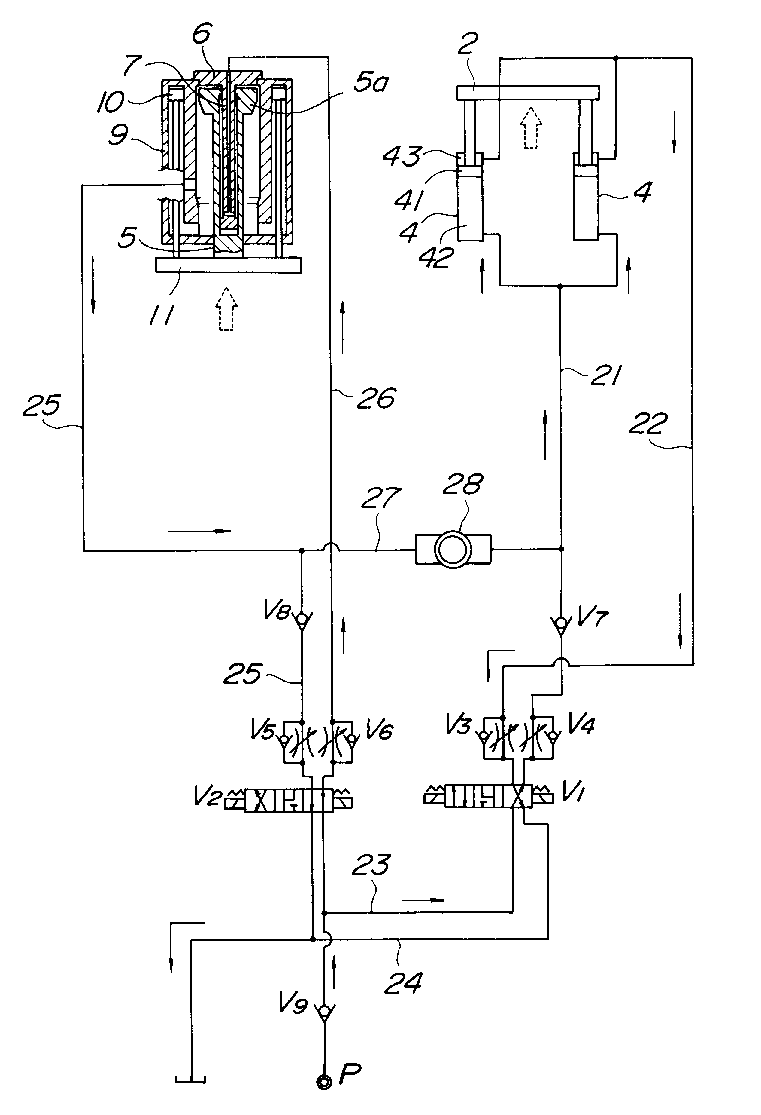
An illustrative example of the volume of one embodiment of the differential mold clamping cylinder as well as the mold opening / closing cylinder according to the present invention is shown below. It is, however, to be understood that the embodiment is not intended to limit the invention in any sense.

As can be seen from the tables above, operating oil for the differential mold clamping cylinder can be supplemented by the hydraulic oil from the mold opening / closing cylinder. Also, it was observed that the mold opening / closing operation was made faster by as much as almost two seconds and simultaneous operation of the cylinders was achieved. This is considered to be due to the fact that the time lag that arises because the hydraulic oil is supplied from the pump is diminished.

While the presently preferred embodiment of the present invention has been shown and described, it will be understood that the present invention is not limited thereto, and that various changes and modifications ma...


PUM

PropertyMeasurementUnit
volumeaaaaaaaaaa
pressureaaaaaaaaaa
inner diameteraaaaaaaaaa

Abstract

A mold clamping apparatus in which hydraulic oil that is forcibly discharged into hydraulic lines from one of two kinds of cylinders, that is, a differential mold clamping cylinder and a mold clamping oil chamber of a mold opening/closing cylinder, is, in an alternating manner, provided to the other cylinder as its operating oil. This feature enables the simultaneous operation of the two kinds of cylinders as well as reduction in operating time in which the mold is opened or closed. The mold clamping apparatus includes a stationary mold, a movable mold which closes with respect to the stationary mold, a core movable through the movable mold into and out of the stationary mold. The movement of the core into and out of the stationary mold is effected by a differential mold clamping cylinder which is separate from a mold opening/closing cylinder for the movable mold and is fitted with a booster ram. A hydraulic line on the mold opening side of the mold opening/closing cylinder and a hydraulic line for the differential mold clamping cylinder are interconnected to one another via a communication passage with a pressure/flow control valve disposed thereon. While the movable mold is opened and closed and the core is moved into and out of the stationary mold, a volume of hydraulic oil that is discharged into these hydraulic lines is alternately provided to the mold opening oil chamber or to the differential mold clamping cylinder.

Description

1. Field of the InventionThe present invention relates to a mold clamping apparatus, and more particularly, to a mold clamping apparatus having a movable core for use in injection molding for making molded products such as preforms, which clamping apparatus includes hydraulic circuits that enable reduced operating time in which molds are opened and closed.2. Description of the Prior ArtThe mold clamping apparatus of the type having a stationary mold to form a body of molded products, a movable mold which closes with respect to the stationary mold to form an opening in molded products, and a core which is placed in the stationary mold through the movable mold and is movable into and out of the stationary mold includes those employed in rotary type injection machines disclosed in the publication of Japanese Patent No. 2, 832, 263 which is incorporated herein by reference. In such a mold clamping apparatus, a mold opening / closing cylinder effects opening and closing of the movable mold...

Claims


Application Information

Patent Timeline
Patent Type & Authority Patents(United States)
IPC IPC(8): B29C45/67B29C33/24B29C33/76
CPCB29C45/6771B29C45/67B29C45/6764
Inventor KOBAYASHI, SENTARO
Owner A K TECH LAB INC
Why Eureka
Try Eureka