
Methods of modeling erbium doped fiber amplifiers

a technology of erbium doped fiber and amplifier, which is applied in the direction of instruments, optical elements, active medium materials, etc., can solve the problems of complex wdm system, high loss and high dispersion, and difficult and costly upgrades

Inactive Publication Date: 2002-04-30
LUCENT TECH INC
View PDF6 Cites 11 Cited by
  • Summary
  • Abstract
  • Description
  • Claims
  • Application Information

AI Technical Summary

Problems solved by technology

The challenge in current fiber optic communication systems is to efficiently implement multi-channel, high data rate and / or long distance systems.
In long distance systems (sometimes referred to as "long haul systems") and high data rate systems, it is often a challenge to maintain the modulated signals' integrity because the silica or glass that makes up the fiber optic pipe exhibits high loss and high dispersion characteristics at the wavelength of the light source.
Moreover, the critical challenge for long haul fiber optic communications over distances of more than 100 km is how to efficiently and effectively amplify the optical signals.
The problem with repeaters is that their complex circuitry fixes the electronic speed of each device, making upgrades difficult and costly.
Repeaters also tend to complicate WDM systems and increase their cost because the channels must be amplified one at a time.
Many other models have been proposed for investigating EDF, all of which require rigorous solutions to multi-variable partial differential equations which do not result in exact expressions, and which are computationally complex so that the models require advanced computers and a lot of processor time to solve.
This need has given rise to a multiplexing scheme called "dense wavelength division multiplexing" (DWDM) which has not been well defined by the current models.

Method used


Image

  • Methods of modeling erbium doped fiber amplifiers
  • Methods of modeling erbium doped fiber amplifiers
  • Methods of modeling erbium doped fiber amplifiers

Examples


Embodiment Construction

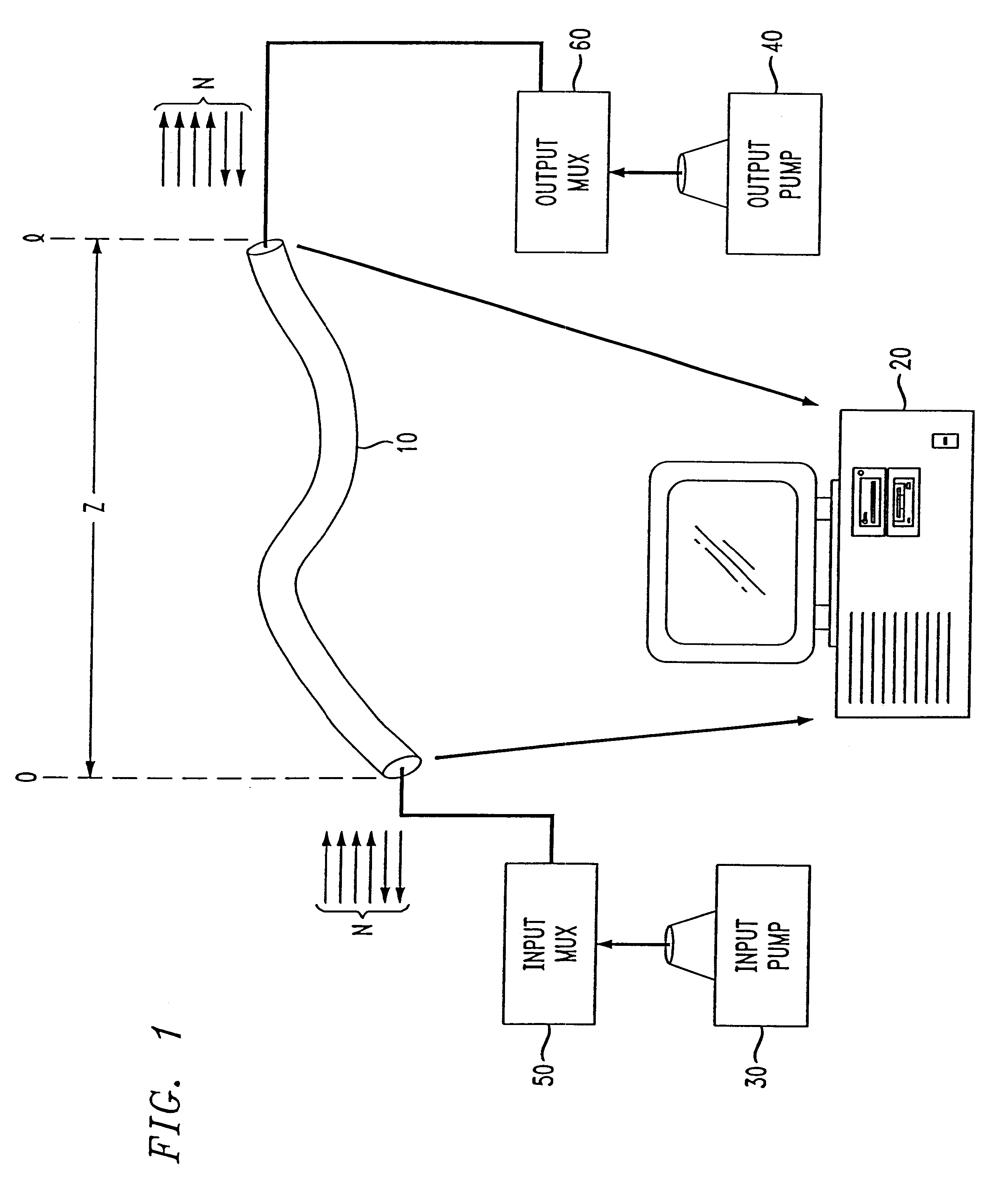
Referring now to FIG. 1, a section of EDF 10 will in the following description and by way of illustrative example be modeled in accordance with the invention using a general purpose digital computer 20. EDF section 10 has a fixed length l which will allow propagation of a plurality of channels N in the direction z of length l. In order to model EDF 10, it is assumed that EDF 10 is pumped with an input coherent source 30, such as a laser, at a first wavelength, and is pumped at the output with an output coherent source 40, such as a laser, at a second frequency. At the transmitter side, an input multiplexer 50 multiplexes the input pumped laser signal to create the N channels and, on the output side, an output multiplexer 60 performs a similar function. The multiplexing may be WDM, DWDM, or any particular multiplexing scheme as appropriate or desired.

EDF 10 comprises a silica fiber which has a core that is doped with erbium atoms that maintain a metastable state when pumped by the la...


PUM


Abstract

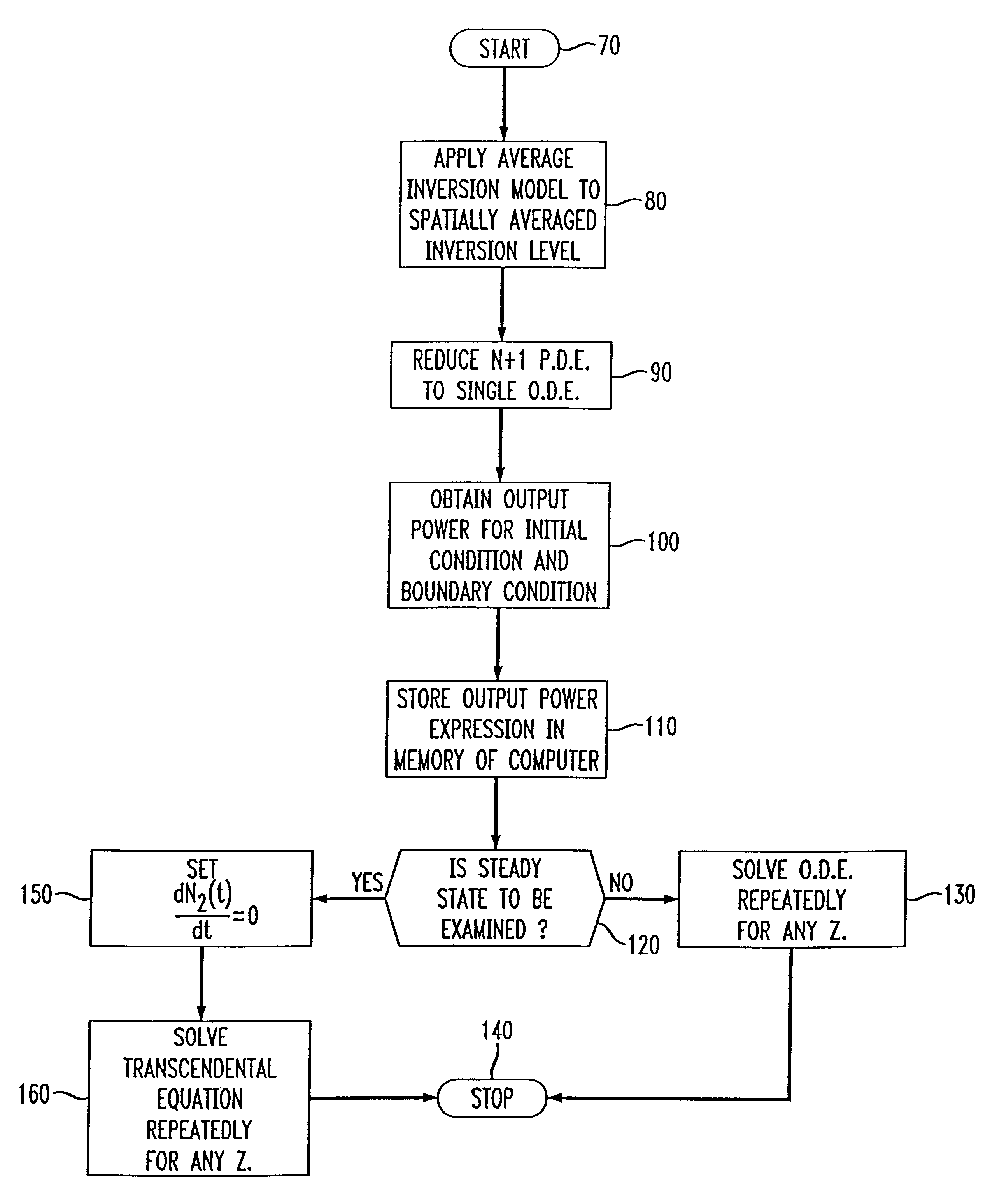
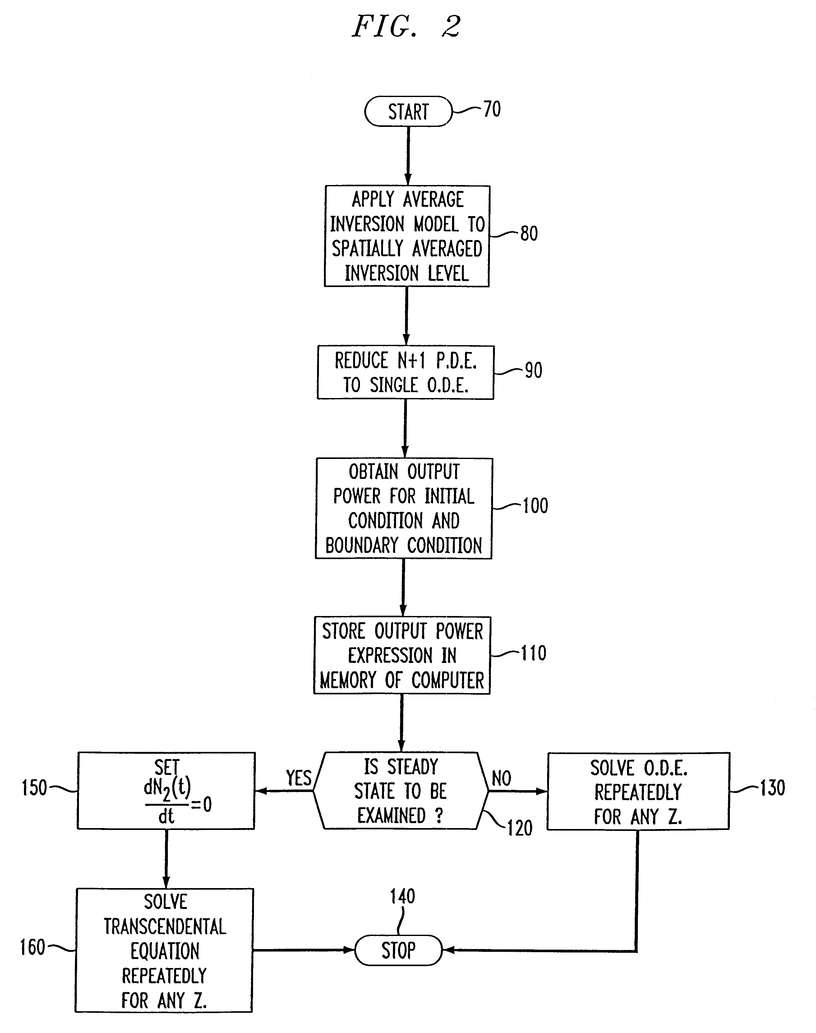
A method of modeling erbium doped fiber ("EDF") for use in erbium doped fiber amplifiers ("EDFA"). The EDF has a length and a fractional population density of erbium ions in an excited state. Since the EDF supports N channels, the power propagation along the EDF is characterized by N+1 differential equations as a function of the direction of propagation, z, of the channels along the length l of the EDF and the time t. By applying an average inversion model to a spatially averaged inversion level of the erbium ions in the fiber, the N+1 partial differential equations are reduced to a single ordinary differential equation. This allows an analytical solution at the boundary and initial conditions of the fiber so that an expression for the power of the signal propagating along the fiber can be obtained. With this expression, the single equation can be solved analytically for the inversion level at any point along the EDF.

Description

1. Field of the InventionThis invention relates generally to methods of characterizing and modeling erbium doped fiber amplifiers (EDFA). More specifically, this invention relates to methods for modeling EDFA having erbium doped fiber (EDF) sections of arbitrary length using a general purpose digital computer to determine at least the average inversion level and output power of the EDFA.2. Description of the Related ArtFiber optic communication methods and hardware have become ubiquitous in our modem age for transporting large amounts of data from one location to another. Fiber optics utilize a light wave as a carrier signal and a modulated light signal to transport the particular information or data to be sent and received. Fiber optic communication systems typically utilize a coherent light source, such as a laser, to provide the carrier and modulation frequencies.Fiberoptic communication also allows for efficient multiplexing of signals. Multiplexing refers to techniques that are...

Claims


Application Information

Patent Timeline
Patent Type & Authority Patents(United States)
IPC IPC(8): H01S3/067H01S3/06H01S3/16
CPCH01S3/06754H01S3/1608
Inventor SHAH, VIRENDRA SSRIVASTAVA, ATUL KUMARSULHOFF, JAMES WILLIAMSUN, YANZHANG, LIYAN
Owner LUCENT TECH INC
Learn More