
Automatic shifting control device for a bicycle

a control device and bicycle technology, applied in the direction of cycle equipment, gears, instruments, etc., can solve the problems of automatic transmission, rapid shifting can be aggravating to the rider, and the lower most gears may not be desired for ordinary use by the rider

Inactive Publication Date: 2002-04-09
SHIMANO INC
View PDF18 Cites 119 Cited by
  • Summary
  • Abstract
  • Description
  • Claims
  • Application Information

AI Technical Summary

Benefits of technology

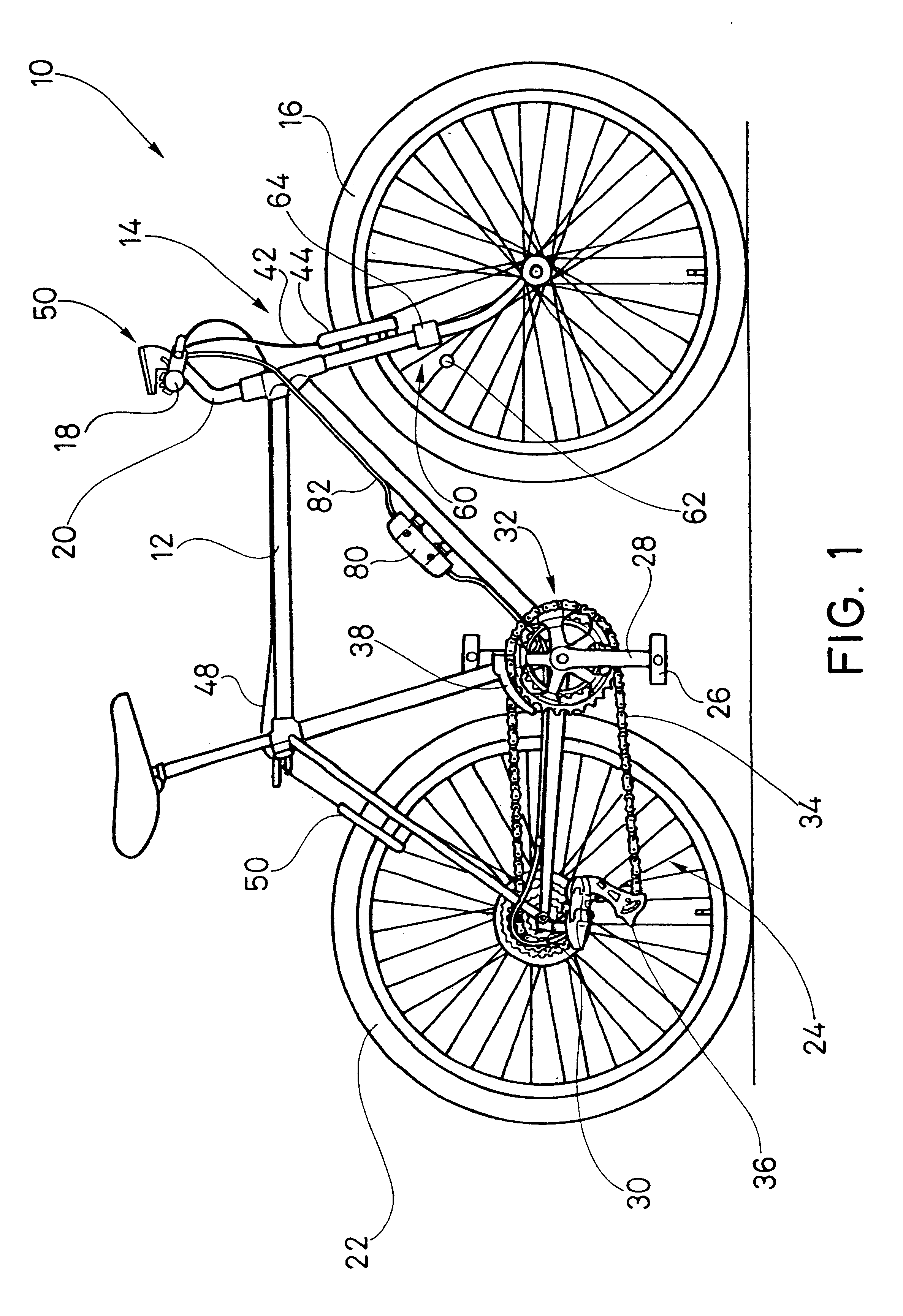
With reference now to FIG. 1, a bicycle is illustrated therein. The bicycle is identified by the reference numeral 10. The illustrated bicycle 10 will provide an exemplary environment in which the present invention can be used. Of course, there are many other types of bicycles and other human-powered vehicles with which certain features, aspects and advantages of the present invention can be used. Accordingly, while the present control device and system will be described in the context of the illustrated bicycle, it should be understood that various features, aspects and advantages of the present device and system also can be used in other environments.
With reference now to the following table, Table 3, a set of cruising mode strategies are illustrated. The illustrated cruising mode strategies can be used in the control system configured and arranged in accordance with certain features, aspects and advantages of the present invention.
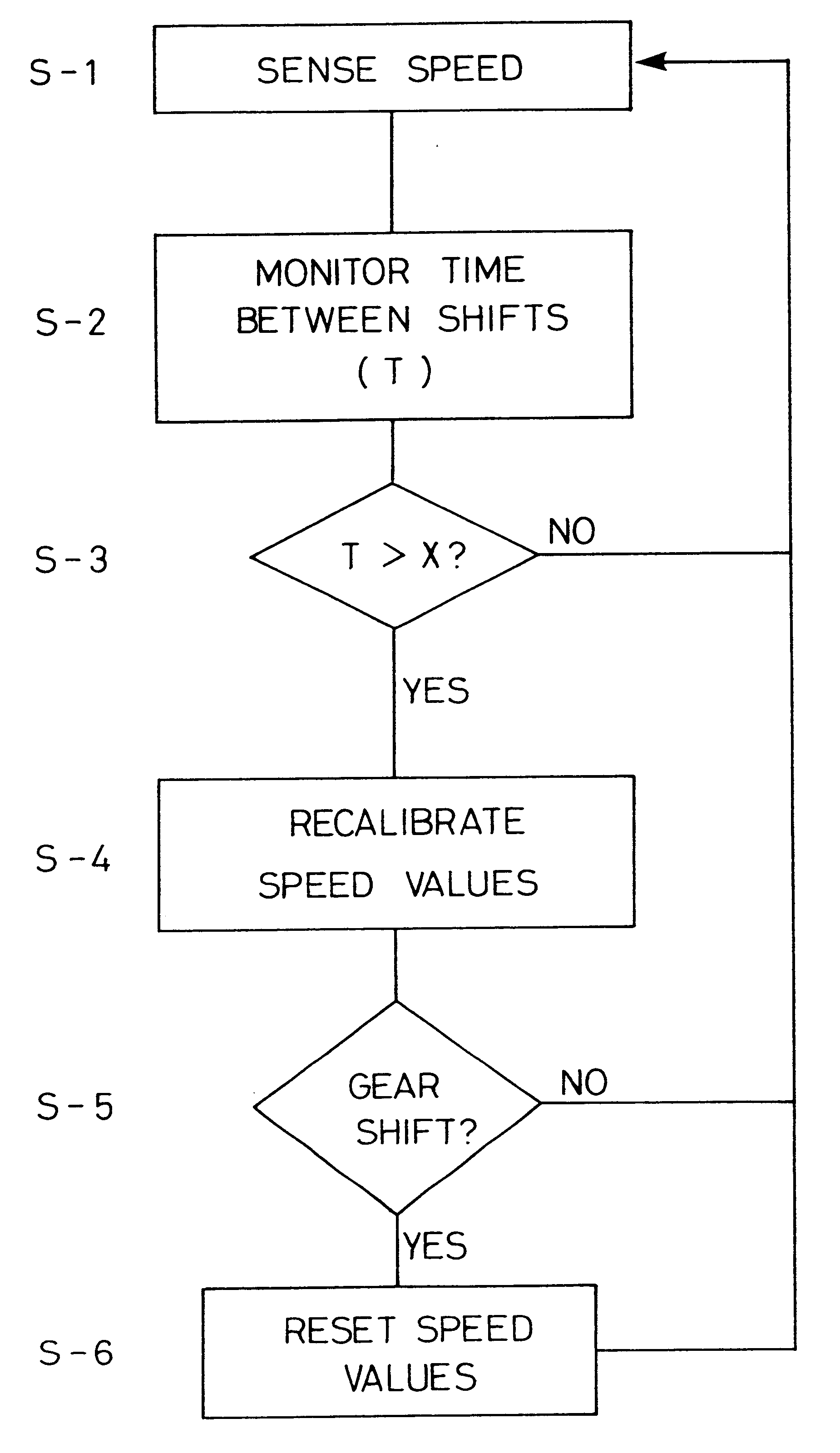
With reference now to Table 3, two cruising modes having certain features, aspects and advantages of the present invention will be discussed. The two cruising modes operate in generally the same manner; however, recalibration of the speed ranges (i.e., max. speed and min. speed) differs between the two cruising modes. Also, it should be noted that cruising mode and automatic mode can be operated regardless of the selected front sprocket.

Problems solved by technology

The large number of available gears, however, causes problems with automatic transmissions.
It has been found that rapid shifting can be aggravating to the rider.
In addition, the lower most gears may not be desired for ordinary use by the rider.

Method used


Image

  • Automatic shifting control device for a bicycle
  • Automatic shifting control device for a bicycle
  • Automatic shifting control device for a bicycle

Examples


Embodiment Construction

With reference now to FIG. 1, a bicycle is illustrated therein. The bicycle is identified by the reference numeral 10. The illustrated bicycle 10 will provide an exemplary environment in which the present invention can be used. Of course, there are many other types of bicycles and other human-powered vehicles with which certain features, aspects and advantages of the present invention can be used. Accordingly, while the present control device and system will be described in the context of the illustrated bicycle, it should be understood that various features, aspects and advantages of the present device and system also can be used in other environments.

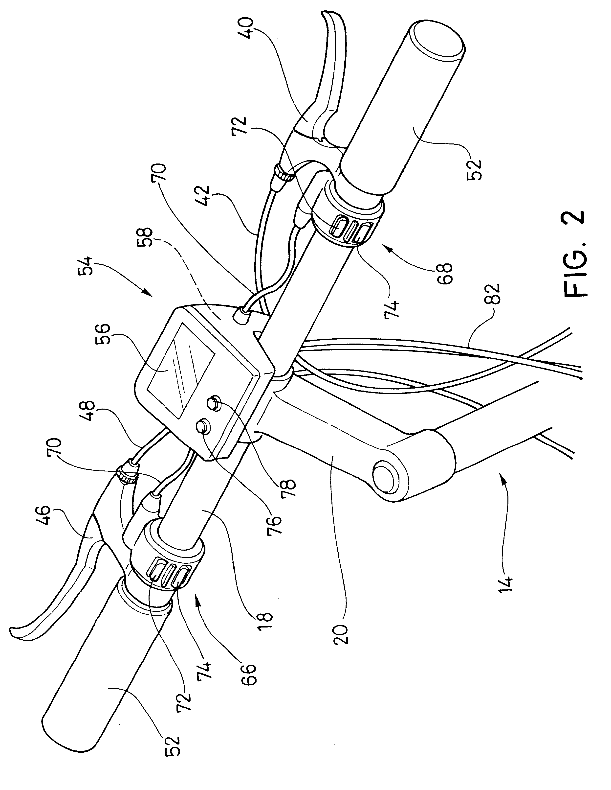
The illustrated bicycle 10 comprises a welded-up frame assembly 12, such as those well-known in the art. A front fork and handle bar assembly 14 is pivotally mounted to a forward portion of the frame assembly 12. A front wheel 16 is rotatably supported within the front fork and handle bar assembly 14. The front wheel 16 can be steered...


PUM


Abstract

A bicycle features an automatically shifting transmission. The shifting is controlled by a controller. The controller has a number of ranges that comprise a subset of the available gear steps. The operator of the bicycle can select an appropriate range and the controller shifts gears within the range depending upon a preset map of bicycle speeds and gear steps. The operator can select other ranges as desired by upshifting or downshifting. The controller also has at least one cruising mode that decreases the likelihood of inadvertent shifting during operation of the bicycle at speeds within a preset range of speeds. In addition, the controller has an elapse mode that further reduces the number of available gear steps in a range during resumed operation after slowing below a preset speed or stopping.

Description

1. Field of the InventionThe present invention generally relates to automatically shifting transmissions for bicycles. More specifically, the present invention relates to strategies for controlling the shifting patterns in such transmissions.2. Related ArtIn recent years, bicycles have begun to incorporate automatic transmissions. The automatic transmissions can be either mechanical or electronic in configuration. In the mechanical type transmissions, centrifugal forces are used to change between gears of the transmission. In electronic type transmission, certain operating characteristics can be sensed and used to signal a desired change between gears. Some of the electronic type transmissions sense operating speed of the bicycle to indicate that a gear change is desired.The automatic transmissions can be used on bicycles featuring increasing numbers of gear steps through which the transmission can operate. For instance, in bicycles featuring a chain drive with a front sprocket set ...

Claims


Application Information

Patent Timeline
Patent Type & Authority Patents(United States)
IPC IPC(8): B62M25/04B62M25/00B62M25/08B62M9/04B62J99/00B62M9/122B62M9/123B62M9/133F16H61/02
CPCB62M9/122B62M9/123B62M25/08B62M25/045B62M25/04
Inventor HORIUCHI, NORIYUKI
Owner SHIMANO INC
Learn More