
Stereo reconstruction employing a layered approach

a layered approach and reconstruction technology, applied in image enhancement, image analysis, instruments, etc., can solve the problems of large volumetric introduction of a huge number of degrees of freedom, insufficient robustness of most techniques, and inability to recover pixel-accurate depth and color information from multiple images

Inactive Publication Date: 2002-02-19
MICROSOFT TECH LICENSING LLC
View PDF7 Cites 70 Cited by
  • Summary
  • Abstract
  • Description
  • Claims
  • Application Information

AI Technical Summary

Benefits of technology

A combination of the global model (the plane) and the local correction to it (the per-pixel depth map) that results in very robust performance and extremely accurate depth maps;

Problems solved by technology

However, the recovery of pixel-accurate depth and color information from multiple images still remains largely unsolved.
However, most techniques are not sufficiently robust and perform poorly around occlusion boundaries and in untextured regions.
However, discretizing space volumetrically introduces a huge number of degrees of freedom.
Moreover, modeling surfaces by a discrete collection of voxels can lead to sampling and aliasing artifacts.
While existing layer extraction techniques have been successful in detecting multiple independent motions, the same cannot be said for scene modeling.
However, it is often undesirable to use a fronto-parallel camera since this may unnecessarily warp the input images.
One unfortunate effect of the blending in Equation (8) is that most forms of averaging tend to increase image blur, particularly when there are a large number of images.
Part of the cause is non-planarity in the scene (which will be modeled in the next section), however image noise and resampling error also contribute.
In this case, the homographic warps used previously are not applicable.
However, corresponding image points in the images that are offset from the estimated plane will warp onto the plane in different locations, thereby reducing the accuracy of the blended layer sprite image.
However, if these images were compared, it would not be possible to deduce anything about the pixel assignments outside of the current estimates of the masked regions.
The danger with working with warped versions of the complete input images W.sup.l.sub.k o I.sub.k is that unoccluded pixels will be blended together with occluded pixels and result in poor estimates of the "full" layer sprites Full L.sub.1.
Such a strategy would still allow the layer masks to grow slightly on each iteration, but, it is believed, limit the influence of occluded pixels in the blend.

Method used


Image

  • Stereo reconstruction employing a layered approach
  • Stereo reconstruction employing a layered approach
  • Stereo reconstruction employing a layered approach

Examples


Embodiment Construction

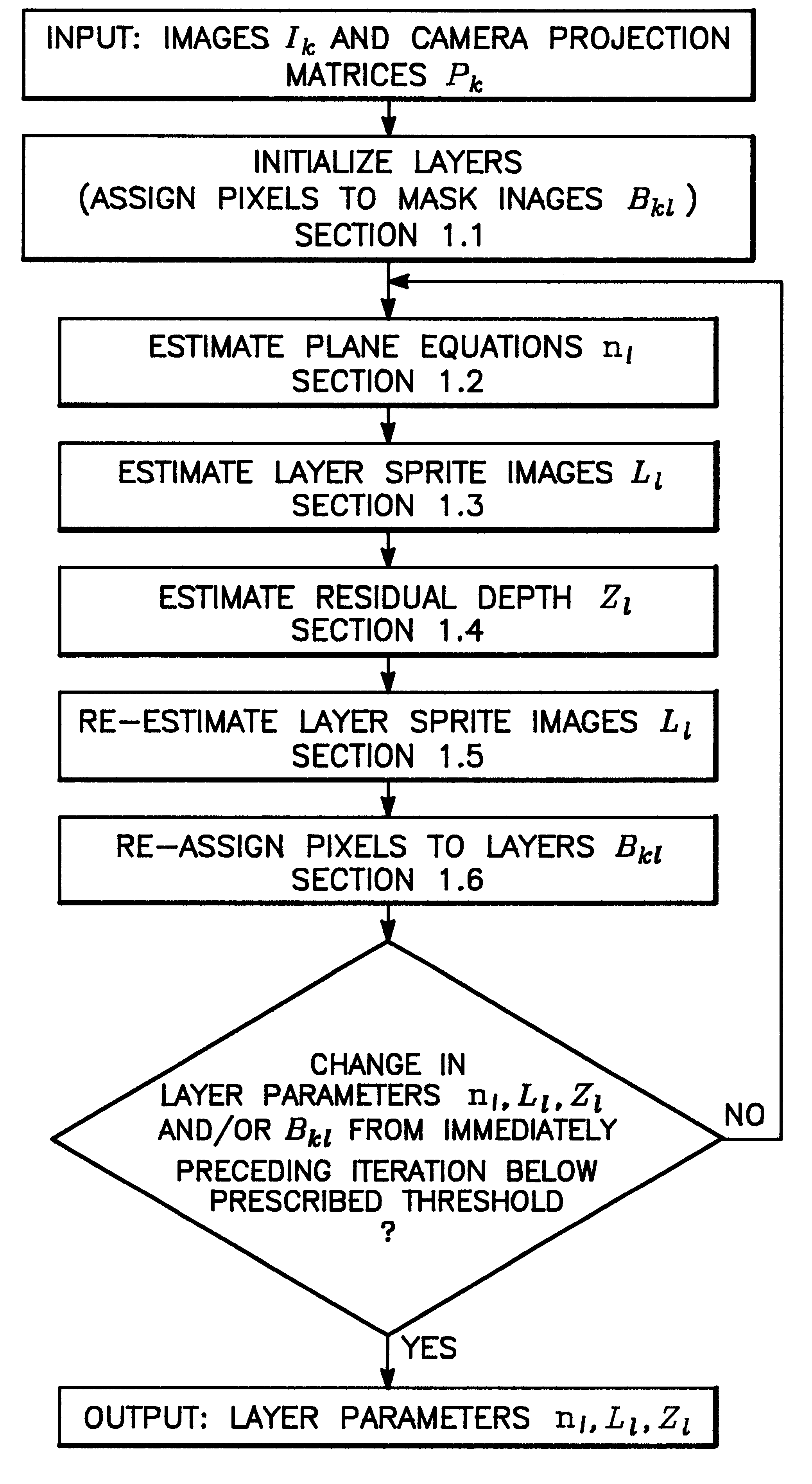
The foregoing estimation process for extracting 3D structure from stereo images was described as including all the program modules depicted in FIG. 3.

Although it is believed the full process will provide the best estimation of the layer parameters L.sub.l, n.sub.l and Z.sub.l ., many applications may not require the high degree of accuracy afforded by the full process. For such applications, some of the modules could be eliminated and still provide the called for resolution. For example, the stereo reconstruction process according to the present invention could be pared down to a five step process involving just the Input, Initializing, Plane Equation Estimation, Layer Sprite Image Estimation and Output modules. In the minimal process, the output would consist of only the plane equation n.sub.l and the layer sprite image L.sub.l . All the other modules depicted in FIG. 3 would be optional. For instance, if a better resolution were required, the Residual Depth Estimation module could...


PUM


Abstract

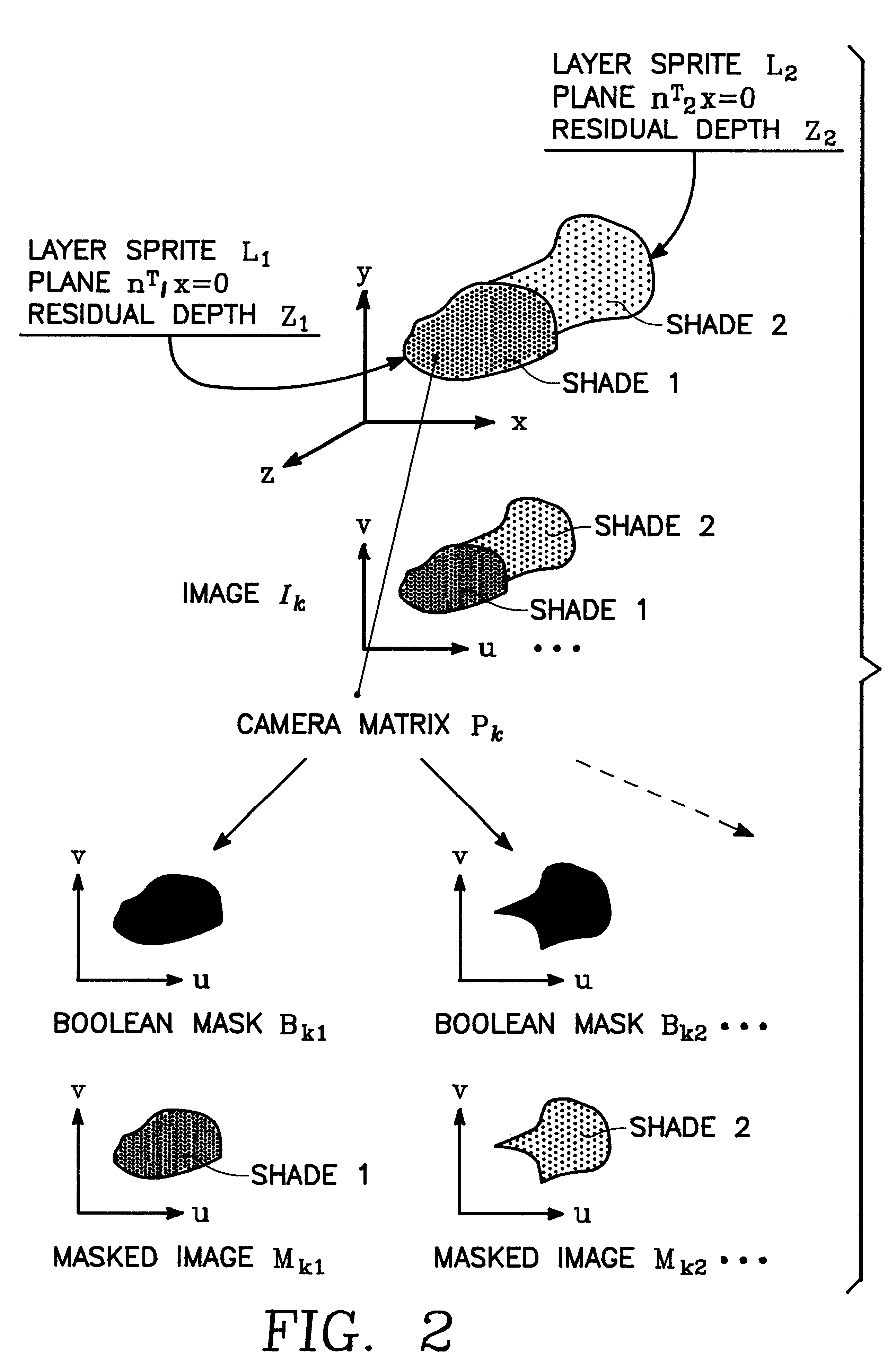
A system and method for extracting structure from stereo that represents the scene as a collection of planar layers. Each layer optimally has an explicit 3D plane equation, a colored image with per-pixel opacity, and a per-pixel depth value relative to the plane. Initial estimates of the layers are recovered using techniques from parametric motion estimation. The combination of a global model (the plane) with a local correction to it (the per-pixel relative depth value) imposes enough local consistency to allow the recovery of shape in both textured and untextured regions.

Description

1. Technical FieldThe invention is related to stereo reconstruction, and more particularly, to a system and process for extracting 3D structure from plural, stereo, 2D images of a scene by representing the scene as a group of image layers.2. Background ArtExtracting structure from stereo has long been an active area of research in the imaging field. However, the recovery of pixel-accurate depth and color information from multiple images still remains largely unsolved. Additionally, existing stereo algorithms work well when matching feature points or the interiors of textured objects. However, most techniques are not sufficiently robust and perform poorly around occlusion boundaries and in untextured regions.For example, a common theme in recent attempts to solve these problems has been the explicit modeling of the 3D volume of the scene. The volume of the scene is first discretized, usually in terms of equal increments of disparity. The goal is then to find the so-called voxels whic...

Claims


Application Information

Patent Timeline
IPC IPC(8): G06T7/00H04N13/00
CPCG06T7/0075H04N2013/0081G06T2207/10012G06T7/593
Inventor SZELISKI, RICHARD S.ANANDAN, PADMANANBHANBAKER, SIMON
Owner MICROSOFT TECH LICENSING LLC
Learn More