
Low drive voltage optical modulator

a low-drive voltage, optical modulator technology, applied in the direction of optics, optical waveguide light guides, instruments, etc., can solve the problems of amplitude modulation and the inability to change the optical length of the resonator

Inactive Publication Date: 2002-01-22
L3 OPTICS +1
View PDF11 Cites 55 Cited by
  • Summary
  • Abstract
  • Description
  • Claims
  • Application Information

AI Technical Summary

Problems solved by technology

The phase-shifted optical signal combines with the non-phase-shifted optical signal at the output waveguide and produces amplitude modulation in the optical signal due to phase mismatch between the signals and the fact that parts of the two optical signals interfere both constructively and destructively.
An AC voltage applied to the resonator may cause the refractive index of the resonator to change, which may cause the optical length of the resonator to change thus imparting a phase-shift in the optical signal propagating therein.
When the phase-shifted signal recombines with the non-phase-shifted signal at the junction of the two arms (i.e., at the output waveguide), the optical signal propagating in the output waveguide and emerging therefrom is amplitude modulated because the optical signals emerging from the respective arms will interfere constructively and destructively due to the phase mismatch between those signals.

Method used


Image

  • Low drive voltage optical modulator
  • Low drive voltage optical modulator
  • Low drive voltage optical modulator

Examples


Embodiment Construction

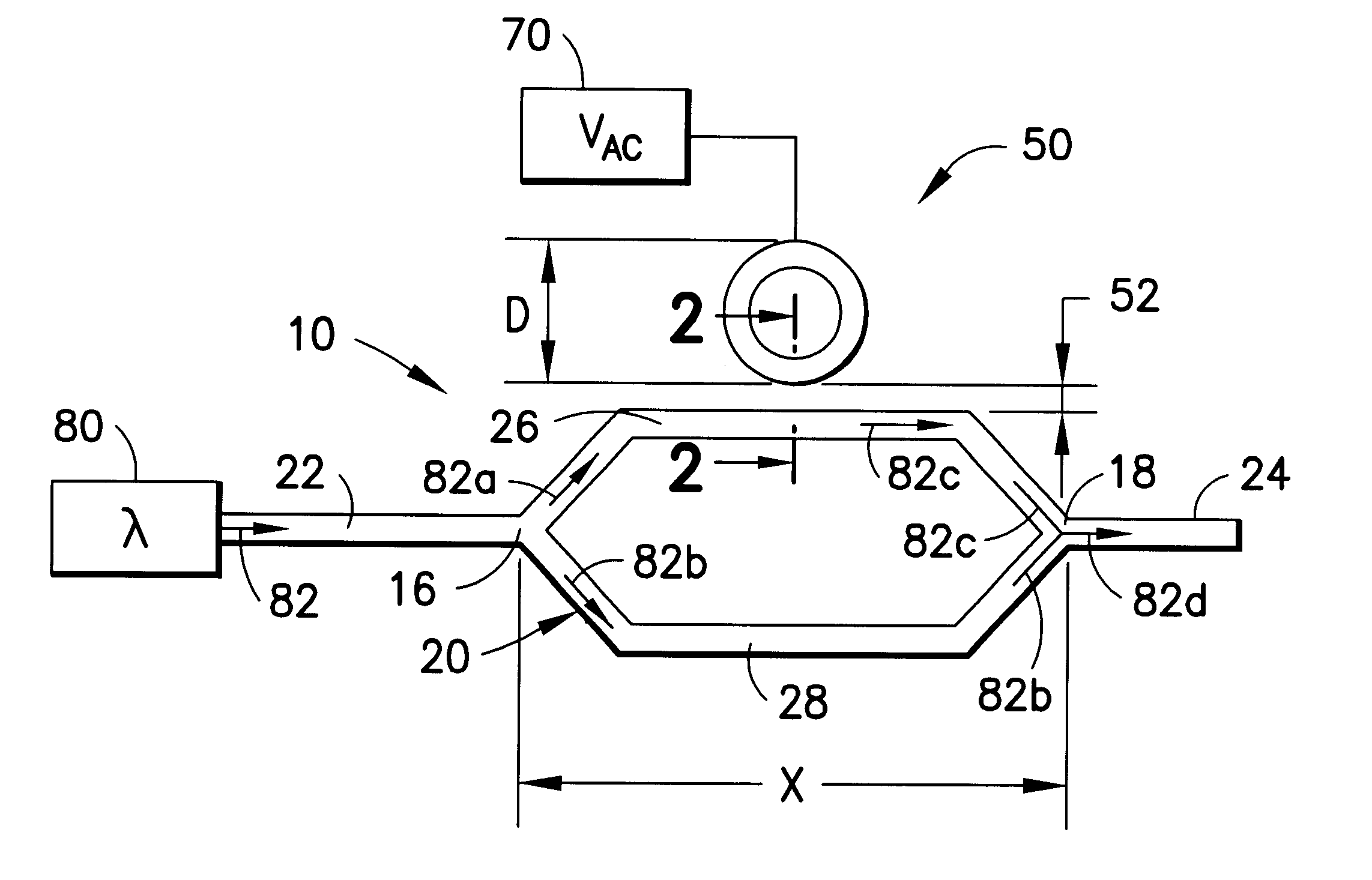
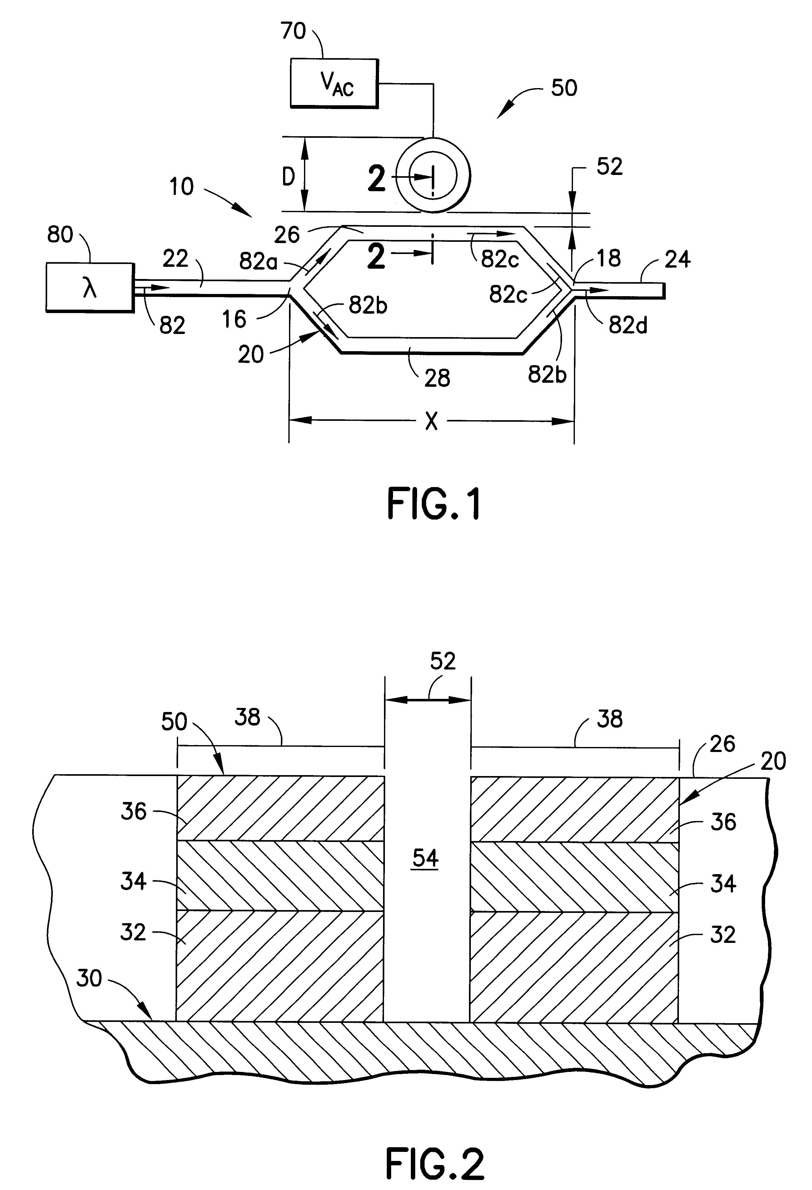
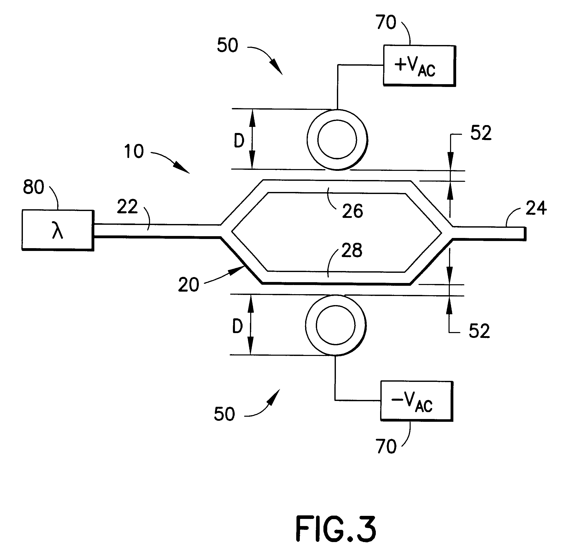
The present invention is directed to an optical modulator comprised of a Mach-Zelinder interferometer having a resonator located near one of the interferometer arms. A portion of the light propagating in the arm near the resonator is coupled into the resonator which is connected to an AC voltage source. By changing the amplitude of the AC voltage, the refractive index and optical path length of the resonator are changed, which causes a phase-shift in the optical signal propagating in the resonator, when compared to the optical signal propagating in the other arm of the interferometer. With a resonator diameter of less than approximately 50 .mu.m, an optical modulator constructed in accordance with the present invention is significantly smaller than prior art modulators. In addition, a significantly smaller drive voltage (i.e., less than approximately 1 VAC) is required to introduce a desired phase-shift (e.g., .pi..degree.) in an optical signal propagating in the resonator and in th...


PUM

PropertyMeasurementUnit
refractive index ncoreaaaaaaaaaa
refractive index nlowaaaaaaaaaa

Abstract

An optical modulator that includes a resonator near one arm of a Mach-Zehnder interferometer and that increases the optical length of that arm so as to introduce a phase-shift in an optical signal propagating in that arm when compared to an optical signal propagating in the other arm of the interferometer. The resonator also increases the electro-optic interaction between an electrical signal (i.e., the source of information in a modulated signal) and the optical devices (e.g., waveguides). A modulator constructed in accordance with the present invention is thus physically small than prior art modulators and requires a significantly reduced drive voltage to impart information on an optical signal.

Description

The present invention is directed to an optical modulator and, more particularly, to an optical modulator that includes a Mach-Zehnder interferometer having a resonator coupled to one arm that increases the optical length of that arm and that also reduces the amplitude of a drive voltage signal required to introduce a phase-shift into an optical signal propagating through the arm to which the resonator is coupled.BACKGROUND OF INVENTIONA typical Mach-Zehnder modulator includes an interferometer having an input waveguide, two arms that branch from the input waveguide, and an output waveguide at the junction of the two arms. An optical signal is directed into and propagates in the input waveguide, and is split between the two arms so that approximately one-half of the input optical signal propagates in each of the interferometer arms. A drive voltage is applied to one arm of the interferometer which changes the effective refractive index of that arm and introduces a phase-shift in an ...

Claims


Application Information

Patent Timeline
Patent Type & Authority Patents(United States)
IPC IPC(8): G02F1/01G02F1/225G02F1/025G02F1/21
CPCG02F1/2257G02F1/025G02F2203/15G02F2001/212G02F1/212
Inventor HO, SENG-TIONGCHIN, MEE KOY
Owner L3 OPTICS
Learn More