
Process for generating voltage pulse sequences and circuit assembly therefor

a voltage pulse sequence and pulse sequence technology, applied in the direction of process and machine control, electric variable regulation, instruments, etc., can solve the problems of high pulsed load on the pulse transformer and switch, relatively poor efficiency, and not inconsiderable component complexity

Inactive Publication Date: 2001-11-27
PATENT TREUHAND GESELLSCHAFT FUR ELECTRIC GLUEHLAMPEN MBH
View PDF18 Cites 52 Cited by
  • Summary
  • Abstract
  • Description
  • Claims
  • Application Information

AI Technical Summary

Problems solved by technology

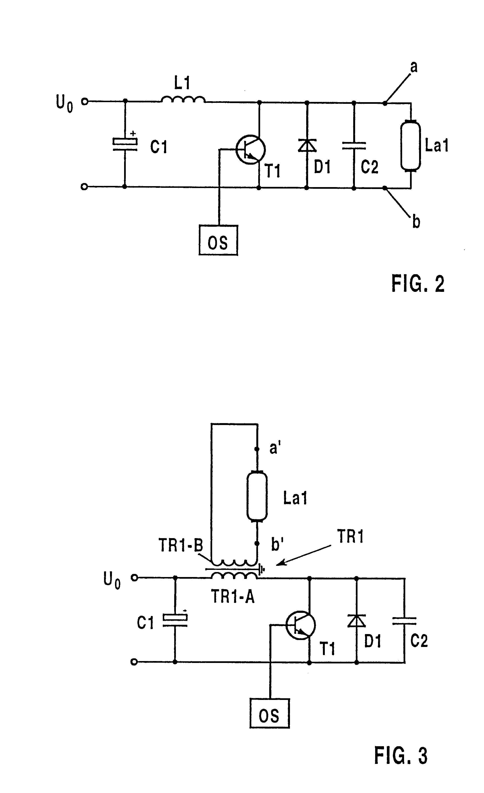
The disadvantages of this solution are the high pulsed load on the pulse transformer and on the switch, the relatively poor efficiency, as well as the not inconsiderable component complexity.

Method used


Image

  • Process for generating voltage pulse sequences and circuit assembly therefor
  • Process for generating voltage pulse sequences and circuit assembly therefor
  • Process for generating voltage pulse sequences and circuit assembly therefor

Examples


Embodiment Construction

The object of the present invention is to provide a circuit arrangement with whose aid largely unipolar pulsed-voltage sequences can be produced, with low circuit losses. In addition, it is intended to be possible to produce pulsed-voltage sequences with pulse shapes that are as smooth as possible on loads which act in a predominantly capacitive manner. A further aspect of the invention is to provide a relatively simple circuit with as few components as possible.

A further object of the invention is to provide a method of producing the above mentioned pulsed-voltage sequences.

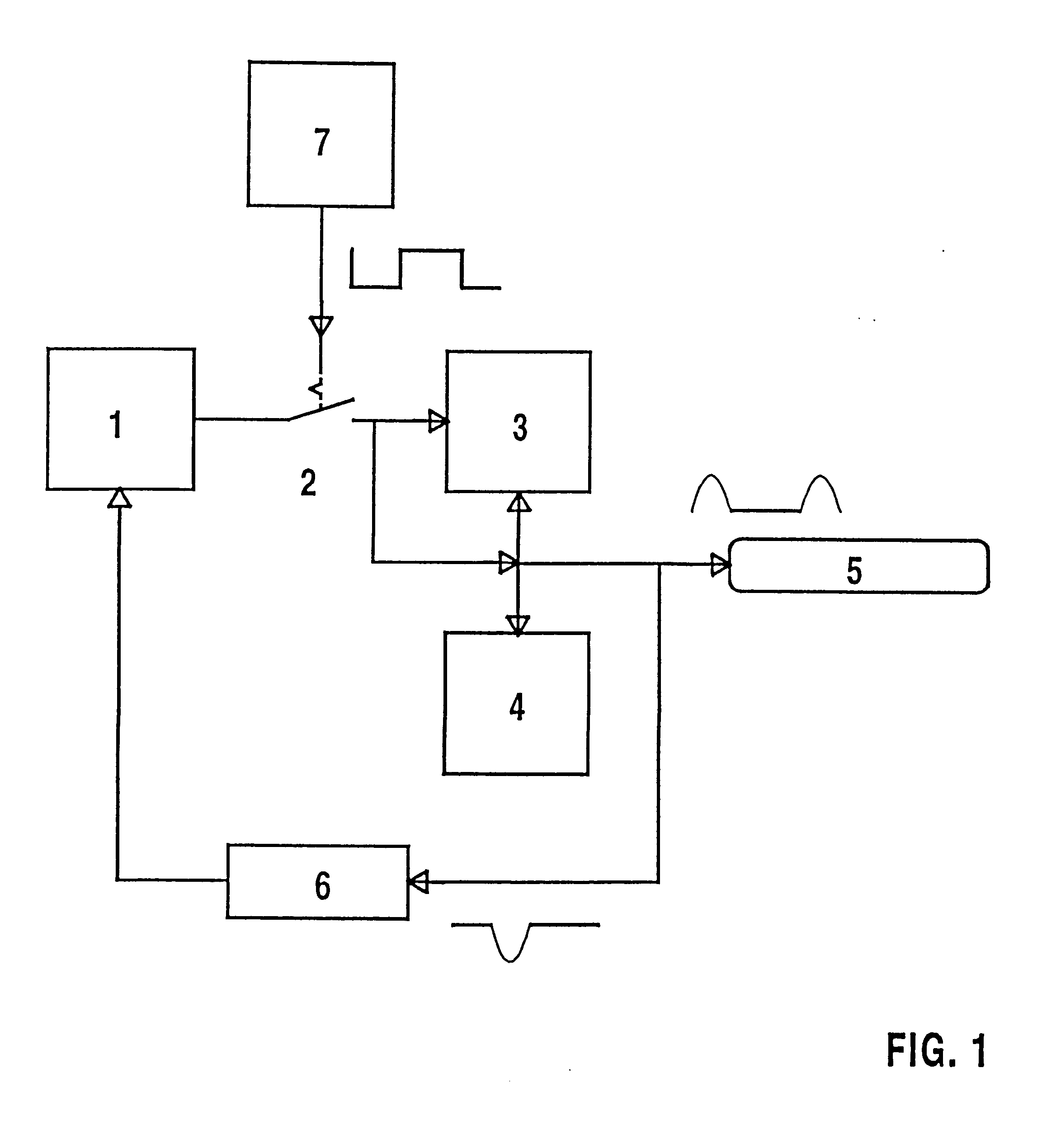
The basic idea of the invention is explained in the following text with reference to a simplified block diagram in FIG. 1. Fed from an energy supply source 1, an inductive energy reservoir 3 is first of all cyclically charged up during the switched-on phase of a controllable switch 2. After the charging-up phase, that is to say as soon as the switch 2 switches off, the magnetic energy stored in the inductive ene...


PUM


Abstract

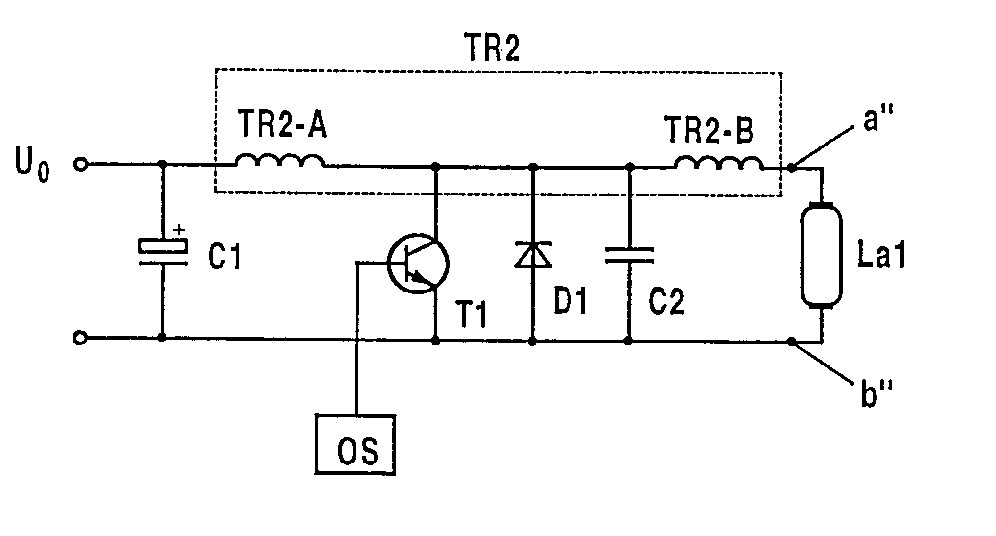
An electrical circuit arrangement for producing pulsed-voltage sequences for the operation of discharges which are impeded dielectrically comprises a series circuit formed from a tuned circuit inductance (TR2-A) and a controlled switch (T1), a pulse generator (OS) which drives the switch (T1), an electrical valve (D1) which is connected in parallel with the switch (T1), a tuned circuit capacitance (C2) which is likewise connected in parallel with the switch (T1), a means (TR2-B, a'', b'') for coupling a lamp (La1) to at least one electrode which is impeded dielectrically, and, optionally, a buffer and feedback capacitor (C1) which is connected in parallel with the series circuit formed by the tuned circuit inductance (TR2-A) and the switch (T1). The means for coupling a lamp comprises in particular two connections (a'', b'') and the secondary winding (TR2-B) of an autotransformer (TR2), which is connected between a first pole of the switch (T1) and the corresponding connection (a''), the primary winding (TR2-A) of the autotransformer (TR2) acting as the tuned circuit inductance. The second connection (b') is connected to the second pole of the switch (T1). In operation, the switch (T1) opens and closes alternately in time with the drive signal of the pulse generator (OS), as a result of which a sequence of voltage pulses, which are separated by pauses, is produced at the electrodes, which are impeded dielectrically, of a lamp (La1) which is connected to the connections (a'', b'').

Description

The invention relates to an electrical circuit arrangement for producing pulsed-voltage sequences for the operation of discharge lamps. The invention further relates to the method in accordance with which the circuit arrangement produces the pulsed-voltage sequences.To be more precise, the circuit arrangement according to the invention is used to operate discharge lamps or radiators in which at least the electrodes of one polarity are impeded dielectrically, by means of unipolar or at least substantially unipolar voltage pulses, such as those described in WO 94 / 23442, for example. This method of operation uses a sequence, which is in principle unlimited, of voltage pulses which are separated from one another by pauses. The critical factors for the efficiency of the wanted radiation production are, essentially, the pulse shape as well as the time durations of the pulse and pause times. Typical duty ratios are in the range between about 1:5 to 1:10. The peak value of the high-voltage ...

Claims


Application Information

Patent Timeline
Patent Type & Authority Patents(United States)
IPC IPC(8): H05B41/28H05B41/24H05B41/282
CPCH05B41/2806H05B41/2881Y02B20/22Y10S315/07Y02B20/00H05B41/30
Inventor STATNIC, EUGENVESER, ALWINERTL, BERNHARD
Owner PATENT TREUHAND GESELLSCHAFT FUR ELECTRIC GLUEHLAMPEN MBH
Learn More