
Piston motor protector, and motor and pumping system incorporating the same

a technology of piston motors and protectors, which is applied in the direction of piston pumps, positive displacement liquid engines, borehole/well accessories, etc., can solve the problems of no longer protecting the motor oil, elastomeric bags suffer from several limitations, and the bag can split or crack

Inactive Publication Date: 2001-10-23
CAMCO INT
View PDF7 Cites 49 Cited by
  • Summary
  • Abstract
  • Description
  • Claims
  • Application Information

AI Technical Summary

Problems solved by technology

However, elastomeric bags suffer from several limitations.
First, the repeated expanding and contraction of the elastomeric bag can cause the bag to split or crack under certain conditions.
Of course, once an elastomeric bag splits or cracks it no longer protects the motor oil from contaminants which are then free to enter and ultimately damage the motor.
Second, elastomeric bags tend to lose their elasticity due to various conditions which may be present in a wellbore.
Eventually the bag will rupture, leaving the contaminants free to attack the motor.
Third, most elastomers cannot survive in environments where the temperature rises above about 400.degree. F.
Above that temperature, most elastomers become brittle causing the bag to break during expansion or contraction.
Many wells contain contaminants, such as hydrogen sulfide for instance, which will permeate the motor protector bag and attack the motor.
In fact, certain contaminants, such as hydrogen sulfide, also tend to alter the chemistry of certain elastomers, causing the elastomers to harden.
Once the elastomer has hardened, the bag eventually breaks.
For instance, certain elastomers may slow the rate at which contaminants such as hydrogen sulfide enter the motor, but they cannot stop the permeation completely.
Alternatively, certain elastomers may exhibit an ability to withstand temperatures as high as about 400.degree. F., but these elastomers tend to have limited elasticity incompatible with the requirements of the motor.

Method used


Image

  • Piston motor protector, and motor and pumping system incorporating the same
  • Piston motor protector, and motor and pumping system incorporating the same
  • Piston motor protector, and motor and pumping system incorporating the same

Examples


Embodiment Construction

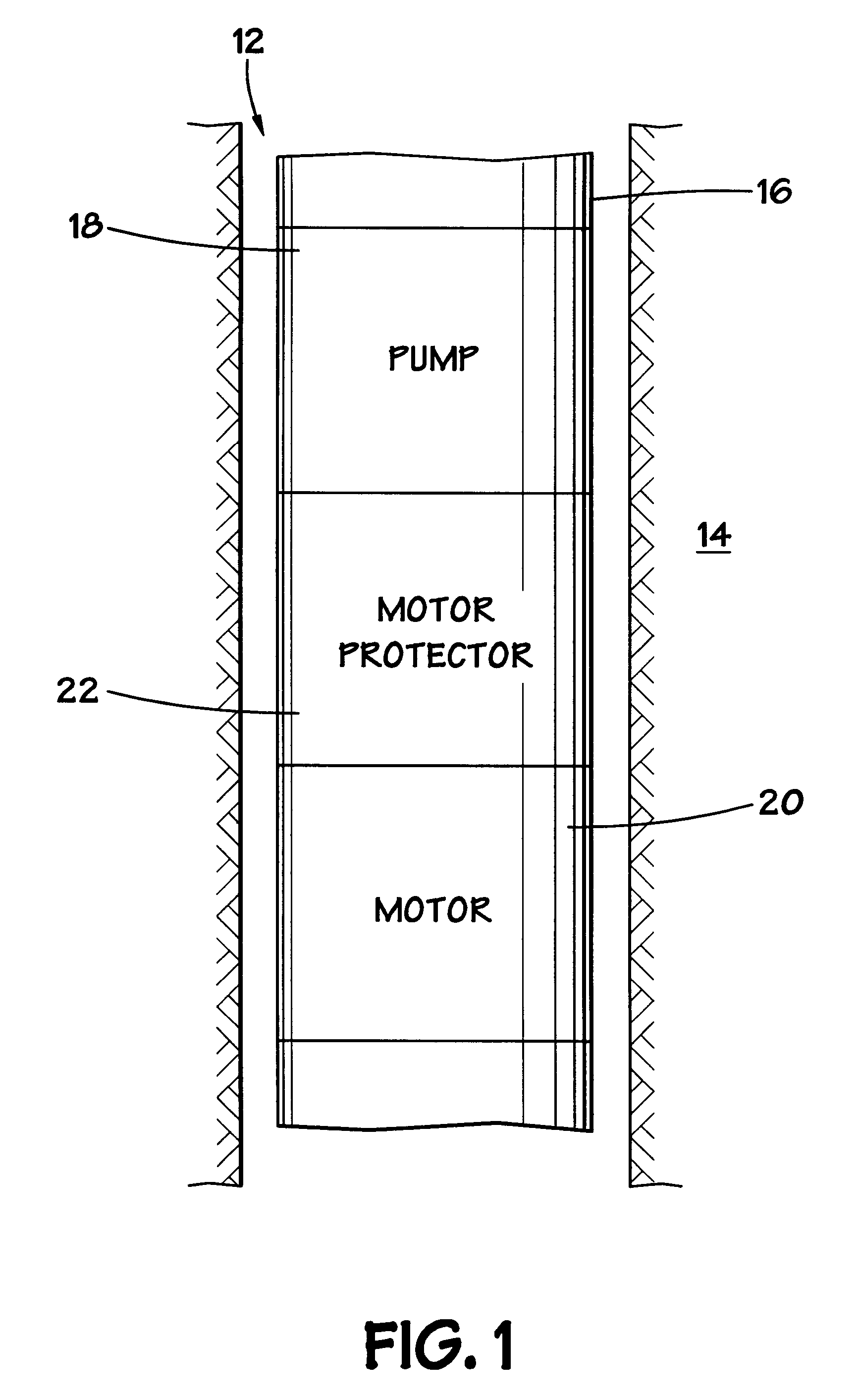
Turning now to the drawings and referring initially to FIG. 1, a pumping system is illustrated and generally designated by a reference numeral 10. The pumping system 10 is shown located in a well bore 12 that has been created within a subterranean formation 14. Although not specifically illustrated, it is well known that the well bore 12 contains fluids and gases from the surrounding formation 14 and that the pumping system 10 is adapted to be submerged in these fluids and gases within the well bore 12.

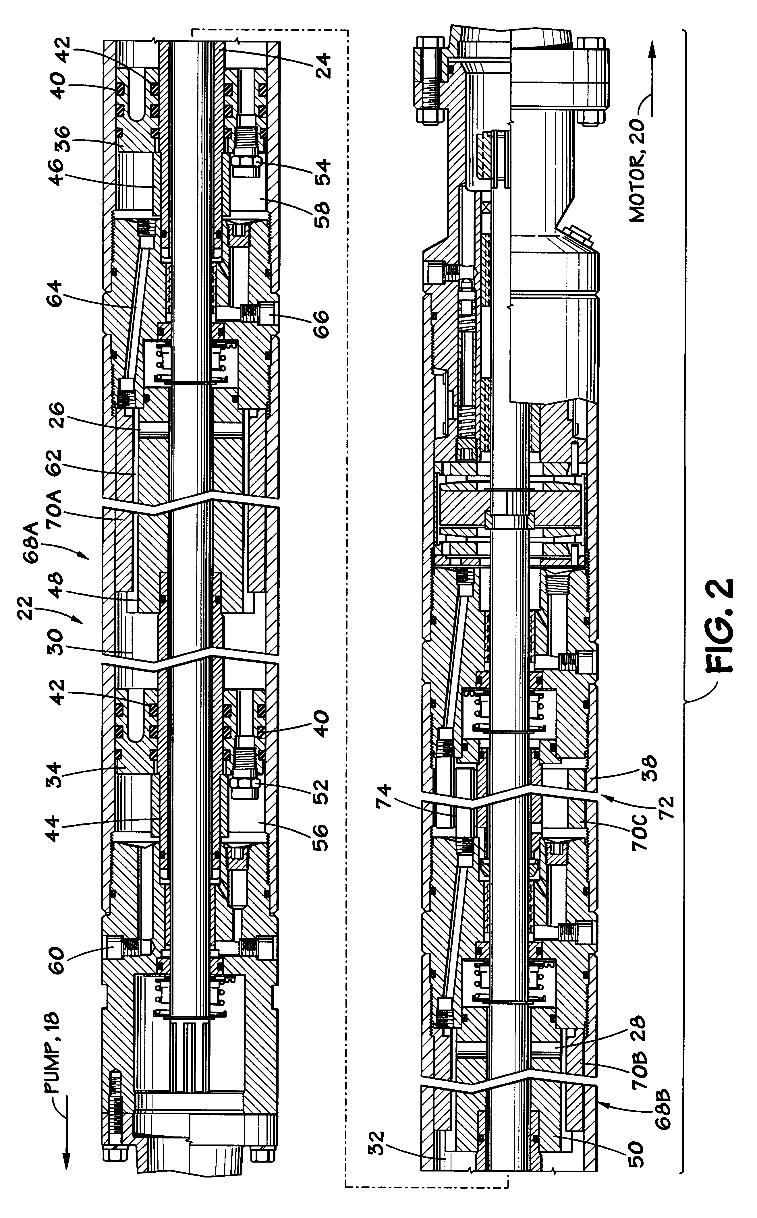
The pumping system 10 is typically part of a production tubing string 16 and is responsible for pumping fluids and / or gases from the well bore 12 to the surface of the Earth. The pumping system 10 includes a pump 18 that is driven by a motor 20. The motor 20 is advantageously an electric motor. The motor 20 contains motor oil (not shown) which lubricates and cools the motor 20. A motor protector 22 is coupled to the motor 20. The motor protector 22 contains a portion of the motor oil,...


PUM


Abstract

A downhole pumping system includes a downhole pump that is coupled to a downhole motor. The downhole motor includes a motor protector that utilizes one or more retractable and extensible pistons, instead of an elastomeric bag, to accommodate motor oil contraction and expansion. The motor protector may also include one or more contamination containment sections for processing contaminants in downhole fluid to reduce contamination of the motor oil.

Description

1. Field of the InventionThe present invention relates generally to downhole pumping systems and, more particularly to a motor protector for use with a downhole pumping system.2. Description of the Related ArtElectric submergible pumps are widely used throughout the world for recovering subterranean fluids to the earth's surface. For the long term successful operation of such submergible pumping systems, the electric motor is supplied with uncontaminated motor oil. The motor oil not only lubricates the motor, it also cools the motor to prevent overheating.In most submergible pumping systems in use today, this motor oil is partially contained within a device commonly referred to as a motor protector. Conventional motor protectors typically include one or more elastomeric bags. These elastomeric bags provide two important functions: (1) equalizing the fluid pressure within the motor and (2) preventing well fluids and gases from contaminating the motor oil.In regard to the first functi...

Claims


Application Information

Patent Timeline
Patent Type & Authority Patents(United States)
IPC IPC(8): E21B43/12H02K5/132H02K5/12
CPCE21B43/128H02K5/132
Inventor SCARSDALE, KEVIN T.
Owner CAMCO INT
Learn More