Systems for setting automatic gun triggering parameters in automated spray coating systems

a technology of automatic spraying and control system, which is applied in the direction of liquid spraying apparatus, coatings, pretreated surfaces, etc., can solve the problems of inability of the operator to watch the spraying operation to confirm the proper coating coverage, the optimal gun triggering parameters are difficult to set, and the triggering system is difficult and time-consuming to configure and re-configure, etc., to achieve easy and rapid setting of the triggering of the spray gun, easy and accurate configuration

Inactive Publication Date: 2001-10-02
NORDSON CORP
View PDF12 Cites 19 Cited by
  • Summary
  • Abstract
  • Description
  • Claims
  • Application Information

AI Technical Summary

Benefits of technology

The present invention overcomes these and other disadvantages and shortcomings of prior art systems. The invention provides an automated coating application system and method in which the spraying parameters for different spray patterns are independently adjusted by the user in order to rapidly and accurately configure the system for optimum coating of a succession of conveyed parts. The automatic gun triggering system of the invention has an automatic gun triggering set-up feature which allows the operator to easily and rapidly set the triggering of the spray guns, by directly observing the movement of parts past the spray guns. The gun triggering settings or parameters are input to a control system through a hand-held mobile pendant having START SPRAY, STOP SPRAY, SAVE and SET PICKOFF input controls.

Problems solved by technology

In prior art systems of this type, the setting of optimal gun triggering parameters is difficult.
For example, if the guns were set to turn on before arrival of a part, this could cause the guns to turn off prior to arrival of the trailing edge of the part at the gun.
One difficulty of this prior art gun triggering procedure lies in the fact that both the Pickoff and the Delay-off are functions of the same variable X. If there is a change in the distance "X", the distance in front of the part that the gun begins spraying, both the Pickoff and the Delay-off parameters must be adjusted and input again into the controller.
This makes this triggering system difficult and time consuming to configure and re-configure especially for different types of parts combined on a single conveyor.
Another problem associated with automated spray systems of the prior art is the inability of the operator to watch the spraying operation to confirm proper coating coverage.
However, since the operator must remain at the control panel, in some installations it is difficult to see from the panel location the parts as they are coated.
This makes it more difficult to properly set the spraying parameters.

Method used


Image

  • Systems for setting automatic gun triggering parameters in automated spray coating systems
  • Systems for setting automatic gun triggering parameters in automated spray coating systems
  • Systems for setting automatic gun triggering parameters in automated spray coating systems

Examples


Embodiment Construction

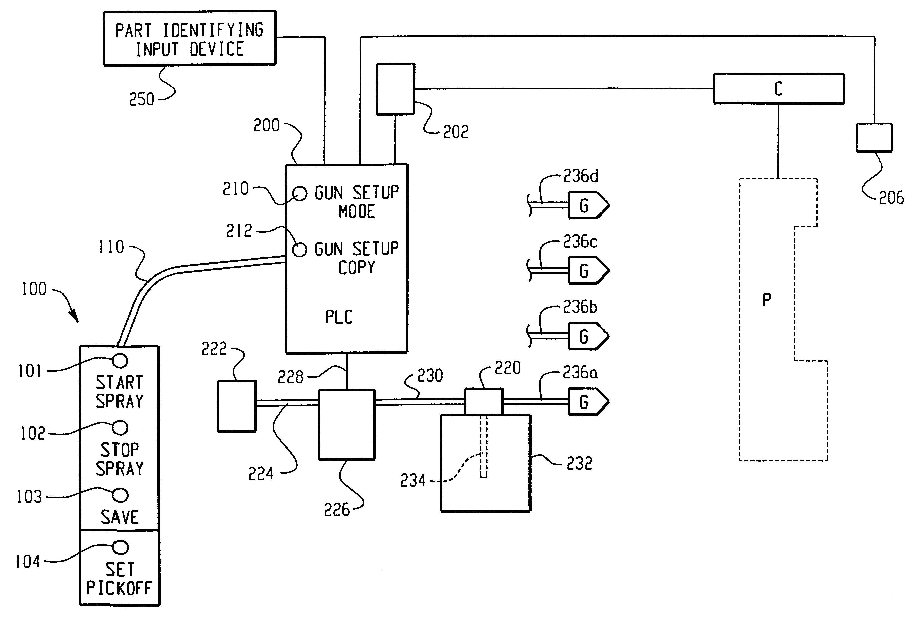
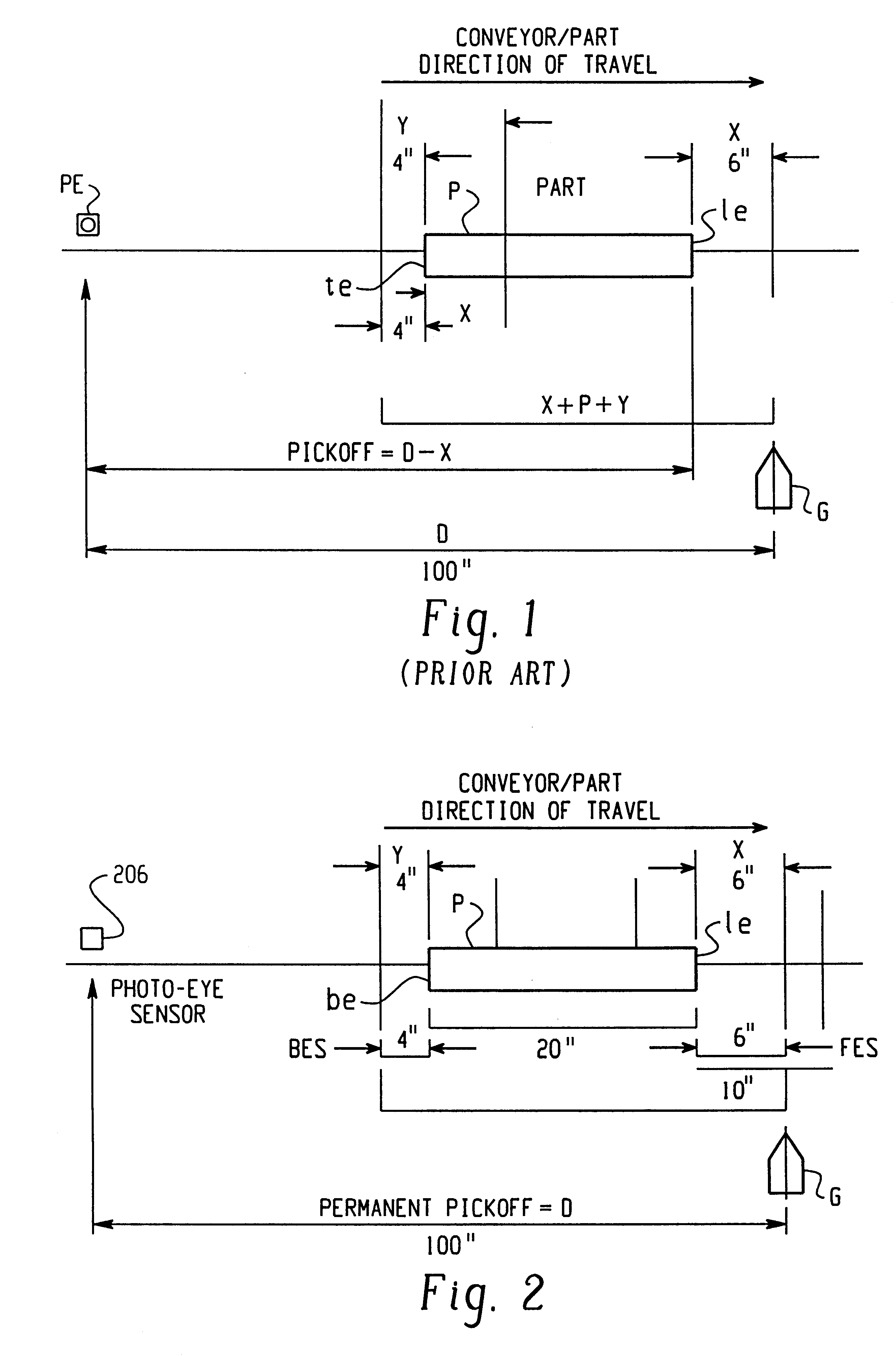
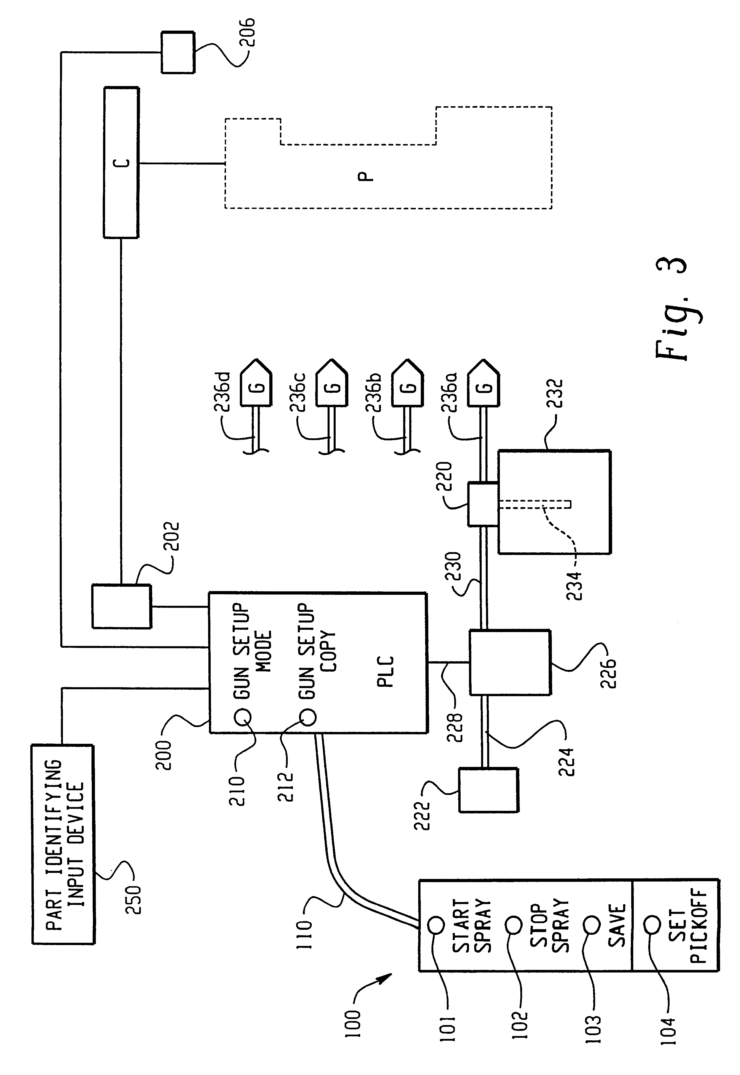
With reference to FIG. 2, the system and method of the invention uses three parameters to establish an optimum spray pattern for any given part or series of parts. The parameters include: 1) a Permanent Pickoff distance D (e.g. 100") defined as the distance from a sensor 206 such as a photoeye to one of the spray guns G of a spray gun array of an automatic spray coating arrangement; 2) front edge spray (FES), which is the point at which the guns will start spraying relative to a front edge of the part; and 3) back edge spray (BES), which is the point at which the guns will stop spraying relative to a back edge of the part. The Permanent Pickoff distance D (also referred to as "Pickoff") is defined as the distance from the sensor 206 to the gun G, which may be, for example, the first gun of an array or bank of guns.

The FES is the distance at which the gun or guns start spraying before the front edge of the part arrives at the gun. An FES greater than zero will cause the gun(s) to sta...


PUM


Abstract

A system and method for controlling triggering of spray guns in an automatic spray coating system, includes a hand-held pendant having input controls for entering spray gun "on" and spray gun "off" control parameters based upon observation of parts as they are conveyed past the spray guns by a conveyor. Gun triggering controls for optimized spray patterns, including extended and restricted spray patterns and combinations thereof, are entered and saved in a gun triggering controller according to an operator's inputs which include START SPRAY, STOP SPRAY, SAVE and SET PICKOFF controls. Multiple gun control parameters are stored as unique part coating recipes in the controller and are executable in look-ahead sequence based upon part identification as parts are conveyed toward the spray guns. The multiple gun control parameters are calculated by the controller from a fixed Pickoff distance from a part identification sensor to the spray guns.

Description

FIELD OF THE INVENTIONThe present invention pertains generally to automated spray or coating systems such as powder or liquid coating systems and, more particularly, to control systems for controlling spray guns in automated coating systems.BACKGROUND OF THE INVENTIONIn automated coating systems, for example of the type having one or more controlled material application spray guns (such as powder spray guns) positioned adjacent to a conveyor which carries parts to be coated past the guns, the guns are controlled (turned on and off and in some cases moved relative to the parts) to apply an optimal spray pattern to parts. Whenever there is a gap between parts on the conveyor, the guns should be turned off to stop spraying in order to minimize waste of material such as powder coating material. The turning on and off of the guns is referred to as "gun triggering". Automatic gun triggering gives the ability to optimize material usage. Automatic gun triggering uses a set of adjustable par...

Claims


Application Information

Patent Timeline
Patent Type & Authority Patents(United States)
IPC IPC(8): B05B12/08B05B12/12B05D3/00
CPCB05B12/122
Inventor COULIBALY, ERICTODD, GENE L.
Owner NORDSON CORP
Why Eureka
Try Eureka