
Mattress construction

a mattress and construction technology, applied in the field of mattresses, can solve the problems of not being able to meet the full edge recovery, the edge region is much stiffer, and the mattress construction is difficult to meet the needs of full edge recovery

Inactive Publication Date: 2001-10-02
WARNER BRADLEY
View PDF4 Cites 95 Cited by
  • Summary
  • Abstract
  • Description
  • Claims
  • Application Information

AI Technical Summary

Benefits of technology

The present invention provides a mattress having a main sleep area surrounded by a border or perimeter trim which does not require hard edge wiring for reinforcement of the perimeter trim. As such, the mattress of the present invention does not suffer from the drawbacks noted above with conventional edge wired mattresses.
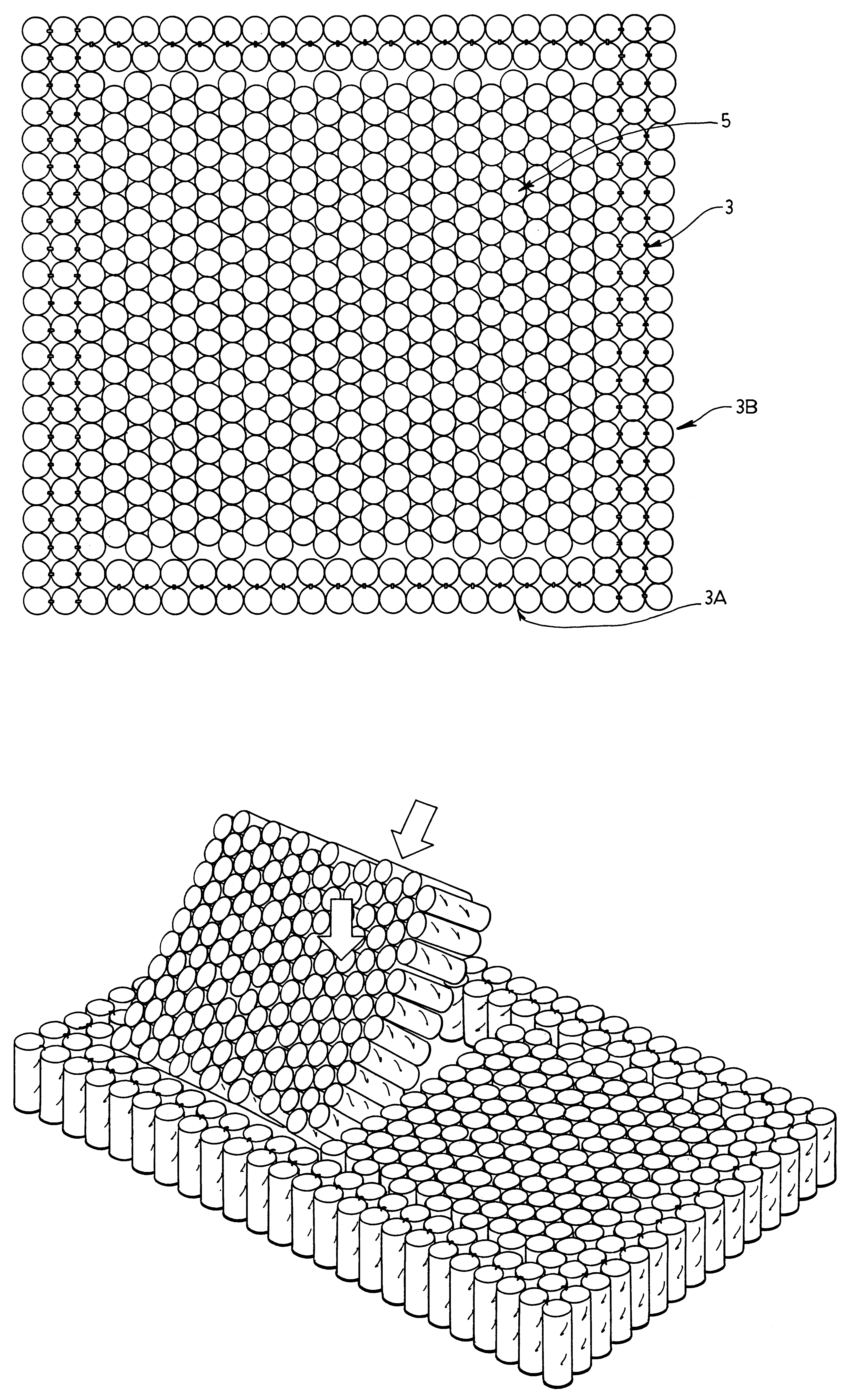
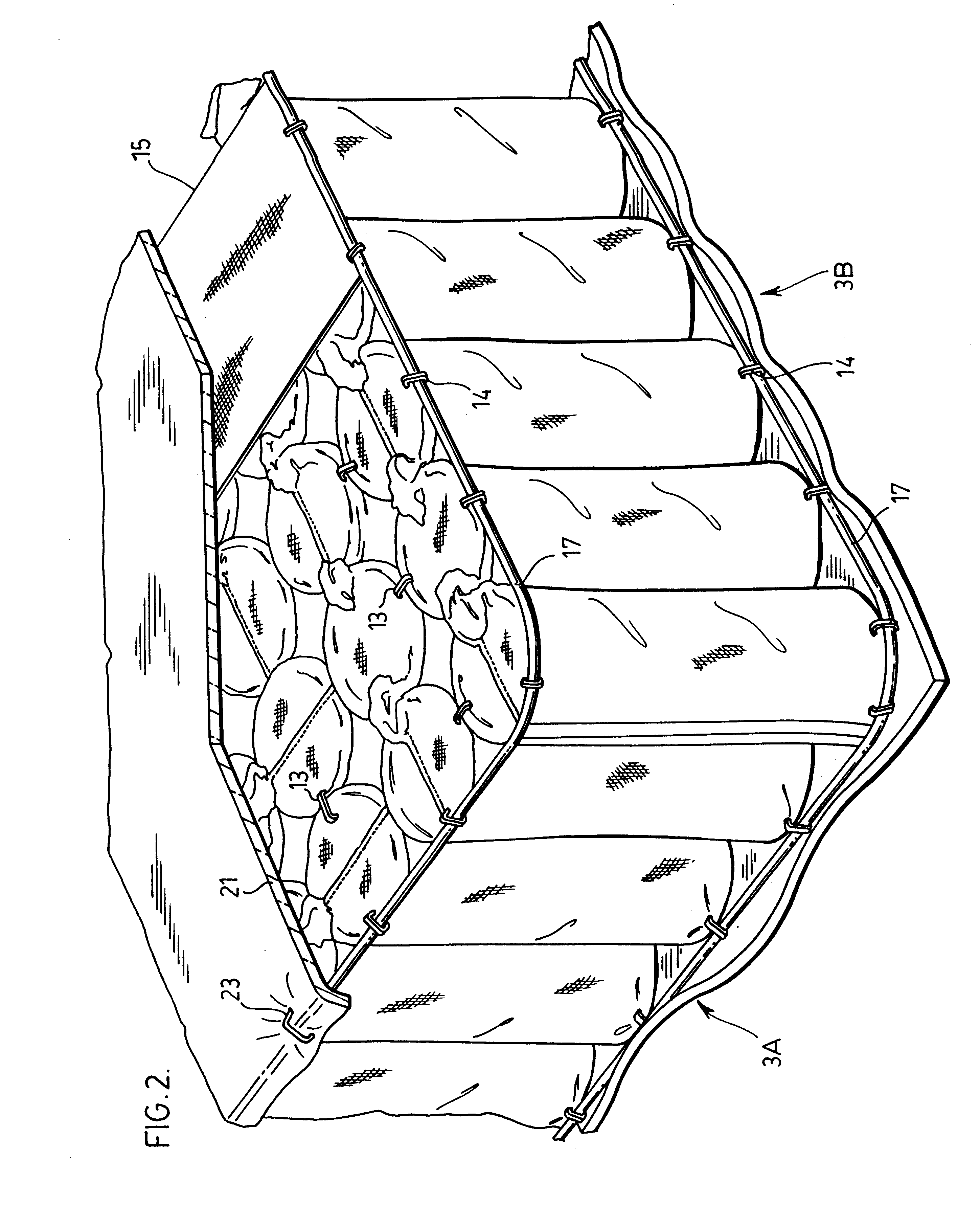
More particularly, the mattress of the present invention is formed by wire springs contained within pockets of soft material in both the main sleep area and the perimeter trim of the mattress. The wire springs in the sleep area are arranged in honeycomb nested rows. The wire springs in the perimeter trim, which are of a different wire construction and have different flex characteristics from the wire springs in the main sleep area are arranged in side by side rows which are not honeycomb nested. Adjacent wire springs across the perimeter trim are pivotally linked directly to one another both widthwise and lengthwise of the mattress. This reinforces the perimeter trim in a manner such that there is no perceptible difference in flex feel between the perimeter trim and the main sleep area of the mattress.

Problems solved by technology

In as much as conventional edge wires contribute to, but not fully satisfy the intended reinforcement of the edge region of a mattress, these same edge wires also result in some disadvantages in the mattress construction.
For example, they produce an edge region which is much stiffer than and uncomfortable relative to the main sleep area in the mattress without necessarily fulfilling full edge recovery.
This therefore decreases the constant usable sleep surface area of the mattress.
In addition, hard edge wires eliminate the possibility of folding the mattress which often becomes necessary when trying to get the mattress through a small access area.
Furthermore, conventional non-foldable mattresses with edge wires cannot be used for the new leisure style folding beds or for multi-position hospital beds and the like.

Method used


Image

  • Mattress construction
  • Mattress construction
  • Mattress construction

Examples


Embodiment Construction

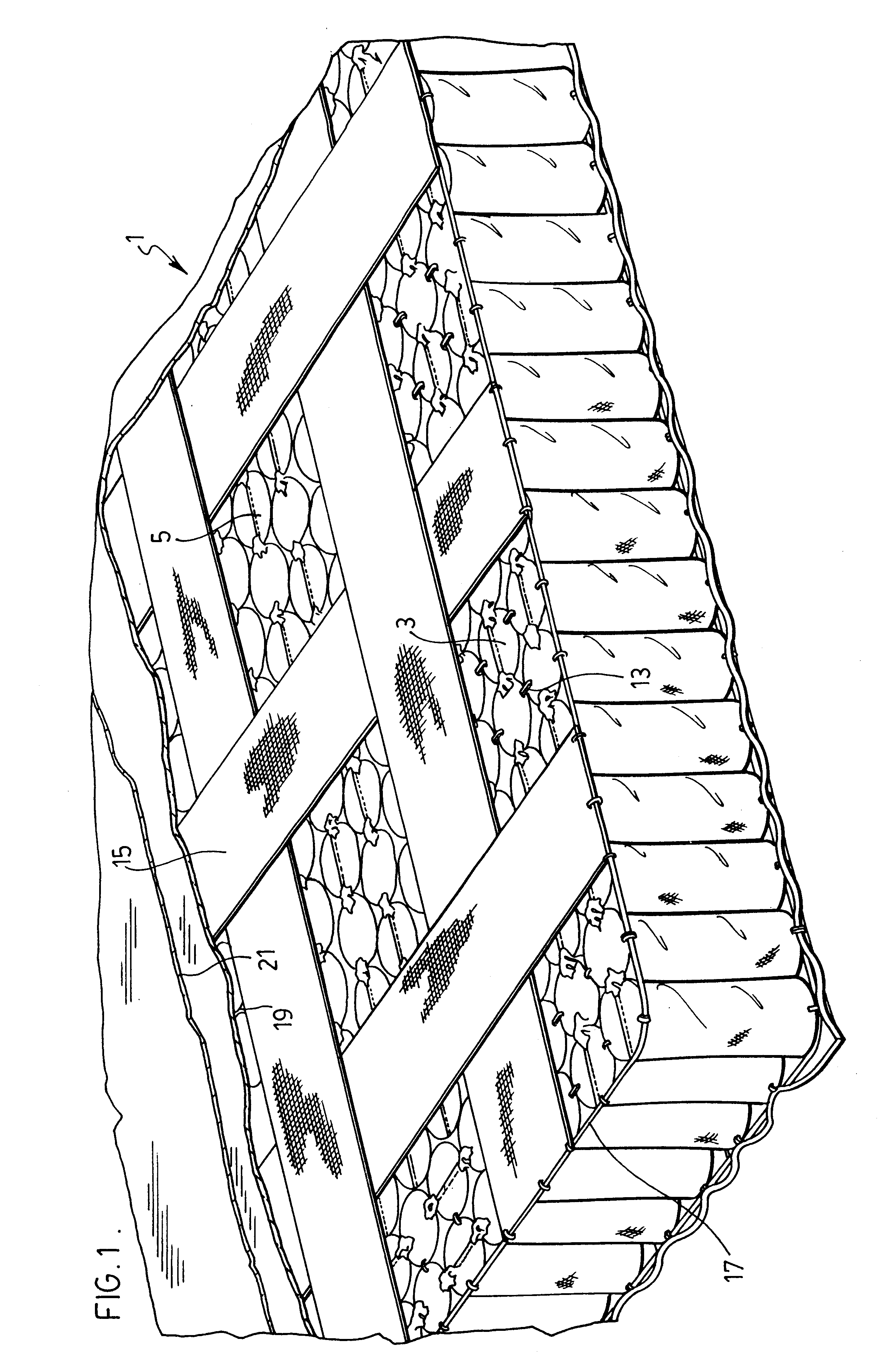
FIG. 1 shows a mattress construction generally indicated at 1. This mattress construction is built around a plurality of individually pocketed springs. FIG. 4 of the drawings shows one of the springs 7 comprising a coiled wire 9 contained within a pocket of soft material 11. This material is sewn at its opposite ends to trap the metal coil in a somewhat compressed condition within the pocket.

In the embodiment shown, a long strip of individual pockets are sewn side by side with one another and each one loaded with a metal coil. This arrangement makes it very easy to assemble the overall mattress as will be described later in detail with respect to FIG. 7 of the drawings.

Returning to FIG. 1, mattress 1 is formed with a border or perimeter trim region generally indicated at 3 which surrounds a larger interior region generally indicated at 5. Even though each of these regions is made up of pocketed springs, the border region is somewhat more flex restrained than the interior region of t...


PUM


Abstract

A mattress has a main sleep area surrounded by a perimeter trim. Both the main sleep area and the perimeter trim are formed from wire springs contained within pockets of soft material. The wire springs in the sleep area are arranged in honeycomb nested rows. The wire springs of the perimeter trim, which are of different wire construction with different flex characteristic from the wire springs in the main sleep area, are arranged in side by side rows which are not honeycomb nested. In addition, the wire springs of the perimeter trim are pivotally linked directly to one another across the perimeter trim, both widthwise and lengthwise of the mattress which produces an essentially non-feelable flex transition between the perimeter trim and the main sleep area of the mattress.

Description

The present invention relates to a mattress formed from pocketed wire springs.Dating back to the late 1890's Marshall Mattress of Toronto, Canada, developed and patented in 1900 a pocket spring mattress. The pocketed springs in the mattress, which have become more and more popular since the advent of the Marshall Mattress are designed to flex individually of one another and as such have extremely appealing flex properties. Accordingly, many years later, other companies in addition to Marshall make pocket spring mattresses.Most mattresses, are provided with a stiffened edge recovery region by adding stiffening components which are not part of the inner spring core.The main sleep area is reinforced by the stiffer edge region. The stiffer edge region does not have anything surrounding it and therefore must rely on its own reinforced characteristics so that it will not break down over time from people sitting on the edge of the mattress.The standard method of reinforcing the edge area o...

Claims


Application Information

Patent Timeline
IPC IPC(8): A47C20/04A47C20/00A47C27/06A47C27/04
CPCA47C20/04A47C27/064
Inventor WARNER, BRADLEY
Owner WARNER BRADLEY
Learn More