
Intelligent boundless computer mouse system

Inactive Publication Date: 2001-09-25
LENOVO (SINGAPORE) PTE LTD
View PDF8 Cites 67 Cited by
  • Summary
  • Abstract
  • Description
  • Claims
  • Application Information

AI Technical Summary

Benefits of technology

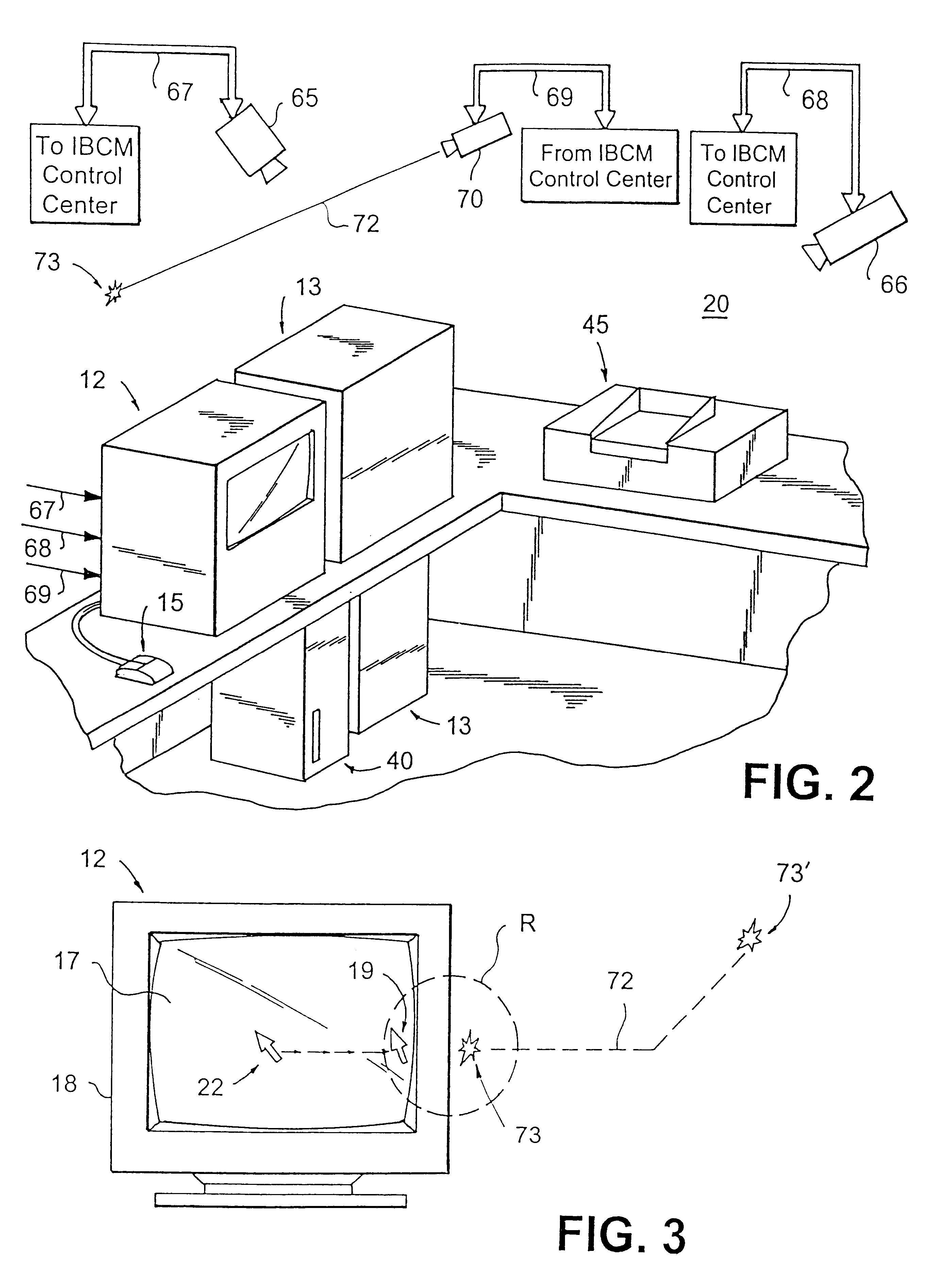
It is another object of the present invention to provide an IBCM device and control system that provides a visual light tracing of IBCM mouse movements after a cursor on the controlling computer crosses the boundaries of an original computer screen on a computer to which the mouse is connected, the light trace and IBCM facilitating activation and / or control of all devices having embedded technologies.

Problems solved by technology

Computer mouse devices employed in personal computers (PCS), workstations, and the like, are limited in the sense that they only are available for controlling events pertaining to a current display on the physical display screen of the monitor connected to the particular computer device.
This creates a problem in obtaining data from different peripheral devices not connected to the computer, e.g., calculator, or other computer screens, LCD displays of palmtop computers, tapes, embedded devices etc., due to the fact that such control requires some kind of connection with the target computer: wire, LAN dial-up, IR, RF, etc.
U.S. Pat. No. 5,832,296 describes a user-wearable interface device in the form of a ring, for enabling interaction with a variety of electronic apparatuses, e.g., computers, by a form of wireless transmission, however, does not enable simultaneous control of several computers / devices, nor enable any other type of interaction, such as copying and moving of data to or from the several devices.
However, the x10 mouse merely communicates with the devices by transmitting pre-defined calls (e.g., using IR or RF) and is incapable of receiving any information.

Method used


Image

  • Intelligent boundless computer mouse system
  • Intelligent boundless computer mouse system
  • Intelligent boundless computer mouse system

Examples


Embodiment Construction

The present invention is an Intelligent Boundless Computer Mouse ("IBCM") system for controlling of one or more computers and devices at a single location, using a single mouse device. The mouse device preferable is provided with intelligence for interacting with software controlling the other computers, at the location, and / or other devices / appliances implementing embedded controller technology.

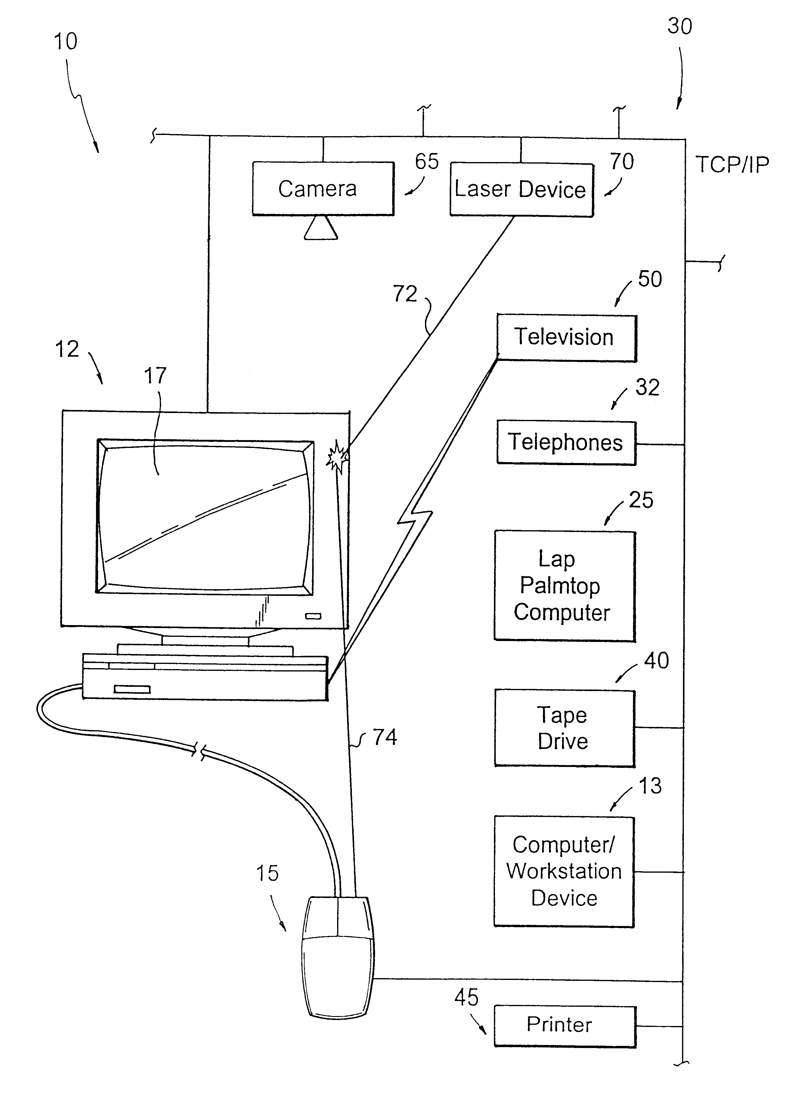
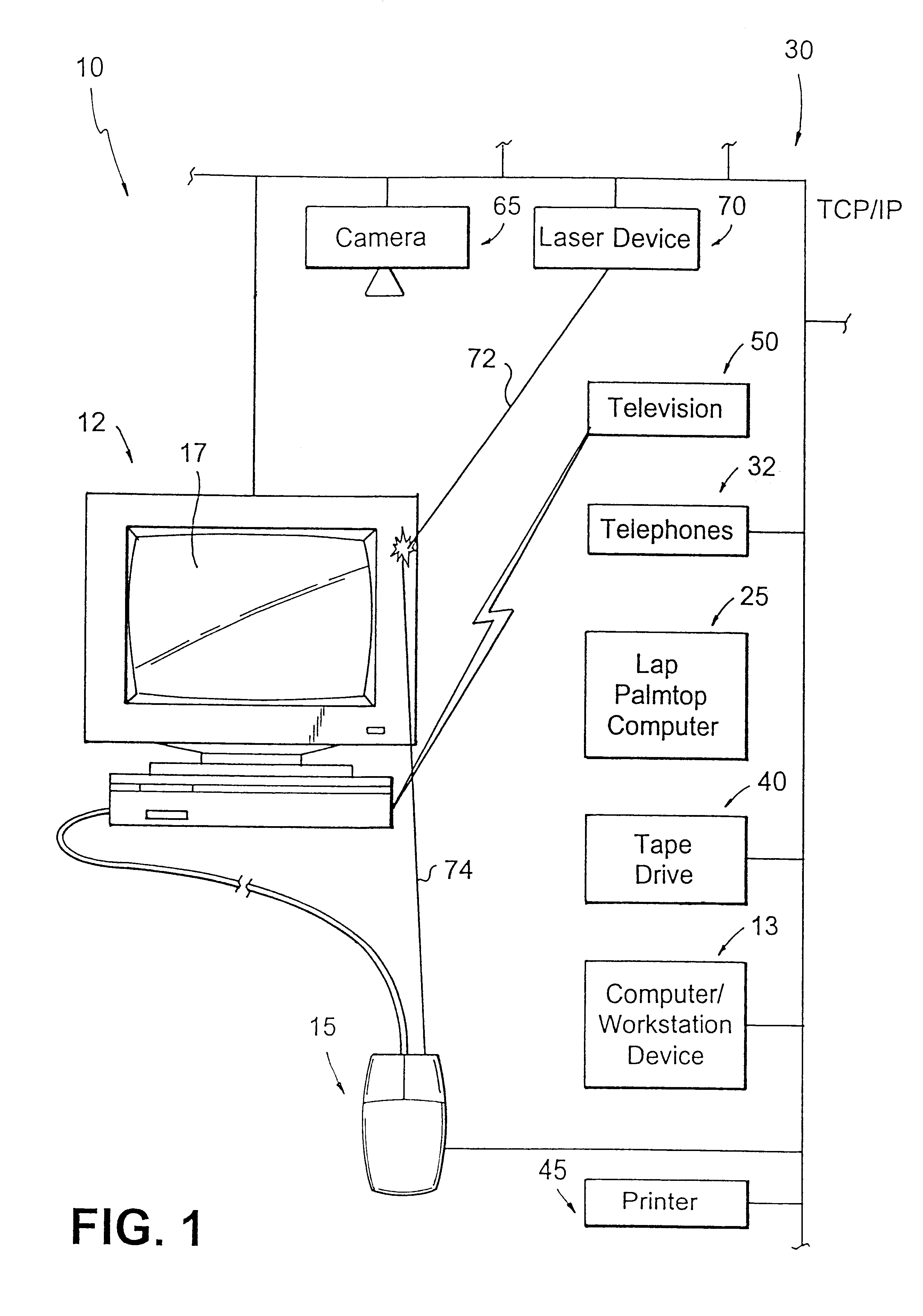
The Intelligent Boundless Computer Mouse ("IBCMN") system 10, as shown in FIGS. 1 and 2, comprises an IBCM control center 12 embodied as a single network PC or server device, for example, and executing software for controlling the office / room 20 and the IBCM system and an IBCM mouse device 15. Preferably, the IBCM control center 12 is integrated as part of a larger network 30 comprising interconnected computers / workstation devices 13, in addition to intermediate devices, including but not limited to: telephones 32, tape drives 40, printers 45, etc. As will be described herein, the IBCM contr...


PUM


Abstract

System and method for controlling of one or more intelligent devices located in proximity with each other at a single location comprises a computer system having screen display terminal including mouse device for providing user-enabled movement of a cursor within a border of the screen display terminal, a detecting system for tracking movement of the cursor and generating a signal indicating when the cursor has reached a border of the screen display terminal; a control system responsive to the signal for tracking further user-enabled movement of the mouse device beyond the screen display border as provided by the mouse device, the control system including: a visual indicator device for providing visual indicator of corresponding cursor movement outside the screen border, and an interactive device for enabling functional operation of an intelligent device pointed to by the visual indicator; the interactive device operating in conjunction with the mouse device for providing activation and functional operation of the other intelligent devices pointed to by the visual indicator.

Description

1. Field of the InventionThe present invention relates to mouse devices for computers, workstations, embedded devices and the like, and particularly to a system implementing a novel mouse device for enabling a greater degree of control over several computers / devices.2. Discussion of the Prior ArtComputer mouse devices employed in personal computers (PCS), workstations, and the like, are limited in the sense that they only are available for controlling events pertaining to a current display on the physical display screen of the monitor connected to the particular computer device. This creates a problem in obtaining data from different peripheral devices not connected to the computer, e.g., calculator, or other computer screens, LCD displays of palmtop computers, tapes, embedded devices etc., due to the fact that such control requires some kind of connection with the target computer: wire, LAN dial-up, IR, RF, etc.U.S. Pat. No. 5,832,296 describes a user-wearable interface device in t...

Claims


Application Information

Patent Timeline
IPC IPC(8): G09G5/08G06F3/038
CPCG06F3/03543G06F3/038G06F3/03545
Inventor KANEVSKY, DIMITRISABATH, MARIUSZZLATSIN, ALEXANDER
Owner LENOVO (SINGAPORE) PTE LTD
Learn More