
Joint for space vehicle

a space vehicle and joint technology, applied in the direction of sheet joining, rod connection, cosmonautic components, etc., can solve the problems of satellite and launch vehicle flanges not being able to separate, design with very high reliability, and prone to self-locking

Inactive Publication Date: 2001-09-18
SAAB ERICSON SPACE
View PDF10 Cites 40 Cited by
  • Summary
  • Abstract
  • Description
  • Claims
  • Application Information

AI Technical Summary

Benefits of technology

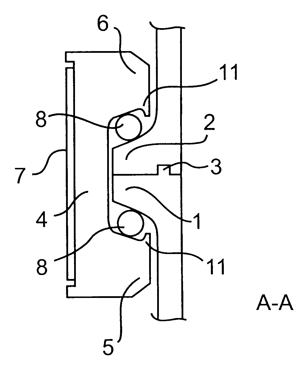
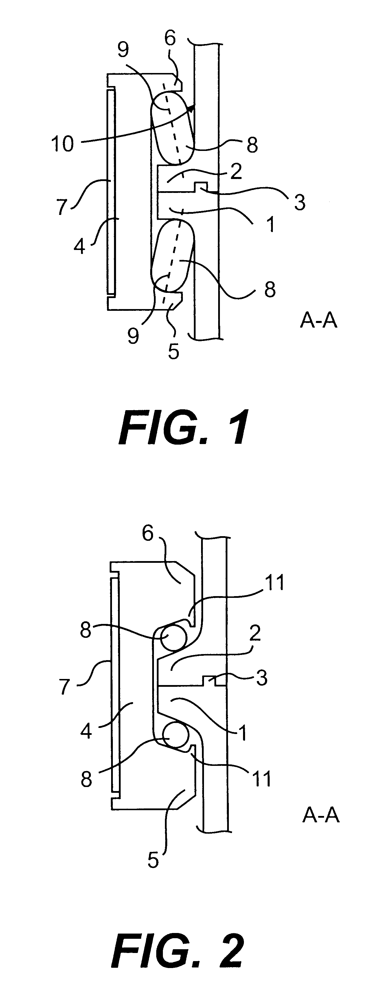
If the rollers are circular cylinders, the same effect as has just been described can be achieved by a design of the surface of the flanges that face outwards towards the clamping lips so that the rollers are forced to roll following a profile on the flange surface. The desired effect can be achieved by suitable design of the profile (the profile need not be the same on the flange as it is on the clamping lip). In this embodiment, the outer part of the clamping lips can be designed with a claw that prevents the roller being pressed out of the space between the flange and the clamping lip.
An alternative design is to arrange a circular cylinder at one of the flanges and an elliptical cylinder at the other flange in order to achieve gradually increasing clamping force.
A significant advantage of the arrangement described from the point of view of the invention is that is becomes possible to achieve a considerable increase of clamping force in the joint at a given tension in the strap relative to that possible using currently available technology.

Problems solved by technology

Such joint devices must be of low weight and must be designed with very high reliability, due to the very high costs of launching and at the same time due to the fact that it is impossible to correct any faults that may arise once the vehicle has left the ground.
If the angle of release is smaller that the said order of magnitude, a risk for self-locking arises, that is, the flanges of the satellite and the launch vehicle are unable to separate due to locking of the clamps against the flanges caused by friction against the clamping lips of the clamps.
Satellites today bear higher and higher loads, and this means that the forces that act on a clamp connection are increasing.
However, difficulties arise in this way in that self-locking may arise, which means that it is not possible with currently available technology to reduce the angle of release significantly.
This alternative, naturally, eventually reaches an upper limit.

Method used


Image

  • Joint for space vehicle
  • Joint for space vehicle
  • Joint for space vehicle

Examples


embodiments

A number of embodiments of the invention are now described, supported by and with reference to the figures.

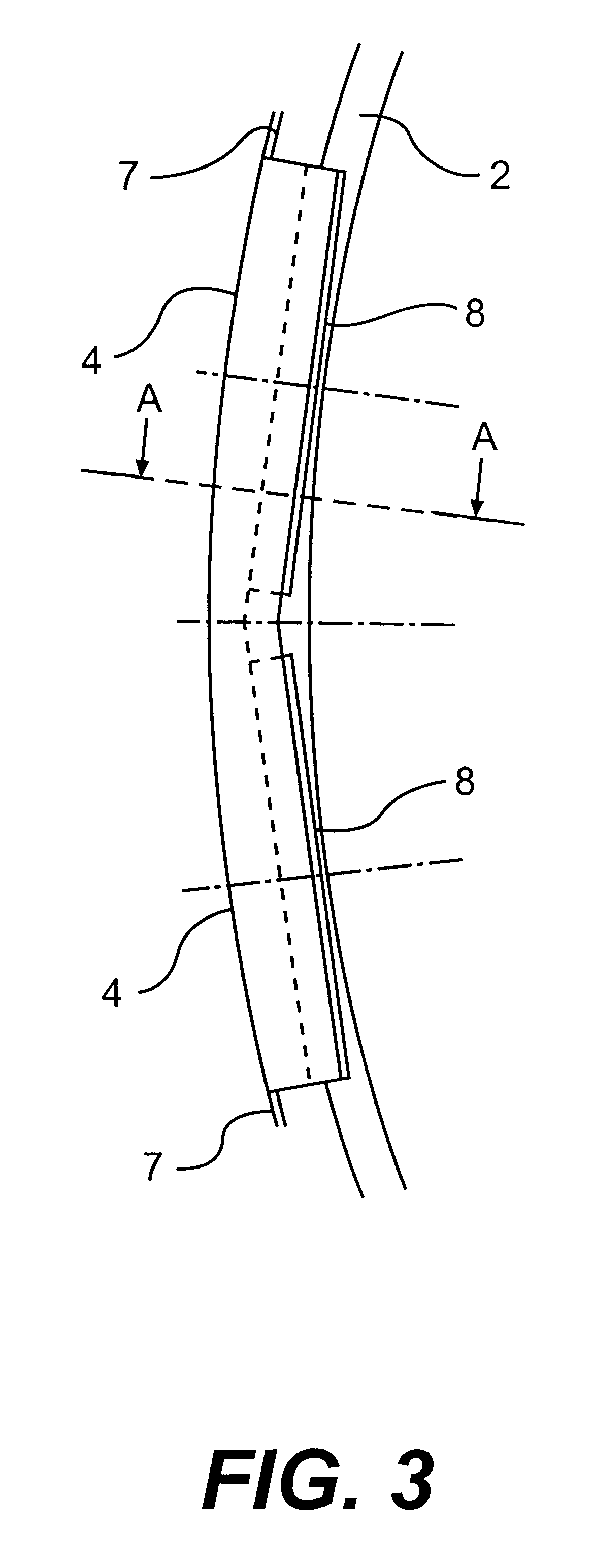
A cross-section of a clamp connection according to the invention is shown in FIG. 1. The parts of the vehicle are here represented by a launch vehicle and a satellite, where an adapter at the top of the launch vehicle has a flange indicated by 1. The satellite is in an equivalent way equipped with a flange 2 at the bottom. The task of the joint is to hold satellite flange 2 and adapter flange 1 together against a plane of division during manoeuvres in a rocket trajectory. In order to control the relationship of the flanges to each other and to absorb shear loading of the joints, the flanges are equipped with a guide 3. Shear loads can also be absorbed by the use of so-called shear pegs, as is currently done in the most common joints. The flanges 1, 2 are according to this example circular, as is shown in FIG. 3, which shows part of the circular flange 2. The flanges 1, 2 encirc...


PUM


Abstract

A joint in a space vehicle to hold together a first part of the vehicle and a second part of the vehicle that can be separated from the first part, in which the joint includes a first flange member (1) attached to the first part of the vehicle and a second flange member (2) attached to the second part of the vehicle. A number of clamps (4) equipped with two clamping lips (5, 6) are distributed around the perimeter of the flange members (1, 2) that transfer radial force from a tensioning means (7), arranged around the clamps (4), to both of the flange members (1, 2) in order to press these together, whereby rolling members (8) are arranged between at least one of the clamping lips (5, 6) of the respective clamps (4) and the adjacent first (1) or second (2) flange member.

Description

TECHNICAL AREAThe current invention relates to a joint to hold together separable parts of a space vehicle preferably during launch of the space vehicle. In particular, the invention is directed towards a joint that includes a number of clamps that are pressed by means of a surrounding strap against flanges that surround the respective perimeters of an adapter ring on each of the separable parts, in which the task of the joint is to hold the said adapter rings together and to be able to absorb the forces that act to separate the separable parts and to absorb torsional and flexural forces that act between the separable parts during the period that the joint is in use.THE PRIOR ARTJoint devices to hold together separable parts of a space vehicle, such as a launch vehicle and a satellite, constitute important structural units to absorb the forces that act between the said parts during launch of the vehicle. Such joint devices must be of low weight and must be designed with very high re...

Claims


Application Information

Patent Timeline
IPC IPC(8): B64G1/64
CPCB64G1/641B64G1/645Y10T403/63Y10T403/648F16B2200/509
Inventor GRUNDITZ, HANS
Owner SAAB ERICSON SPACE
Learn More