Switched power converter with hold-up time and harmonics reduction

a technology of switching power converter and hold-up time, which is applied in the direction of electric variable regulation, process and machine control, instruments, etc., can solve the problems of producing distortion that interferes with the normal operation of other devices connected to the ac power mains, and achieve the effect of reducing the harmonic conten

Inactive Publication Date: 2001-09-11
ALCATEL LUCENT SAS
View PDF7 Cites 12 Cited by
  • Summary
  • Abstract
  • Description
  • Claims
  • Application Information

AI Technical Summary

Benefits of technology

Known techniques, as power factor correction, are used to reduce the harmonics content in the input current, by approximating the input current waveform to a sinusoid, said power factor correction circuits being in general complex.

Problems solved by technology

For performing the conversion switching elements are employed which are switched at high frequency and, as a result, generate harmonics in the input current, possibly producing distortion that interferes with the normal operation of other devices connected to the AC power mains.

Method used


Image

  • Switched power converter with hold-up time and harmonics reduction
  • Switched power converter with hold-up time and harmonics reduction
  • Switched power converter with hold-up time and harmonics reduction

Examples


Embodiment Construction

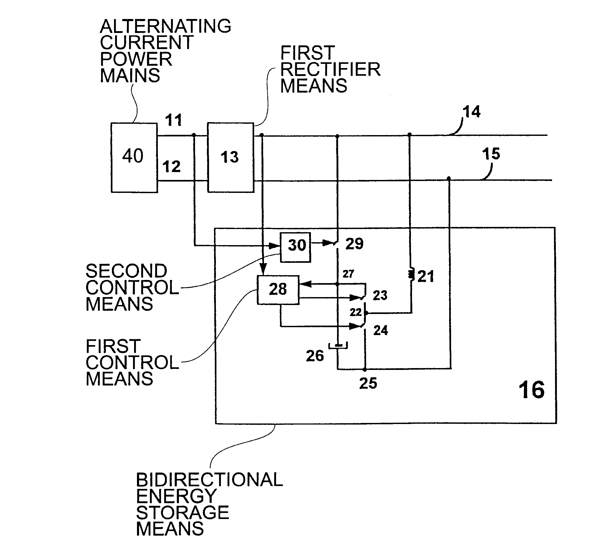
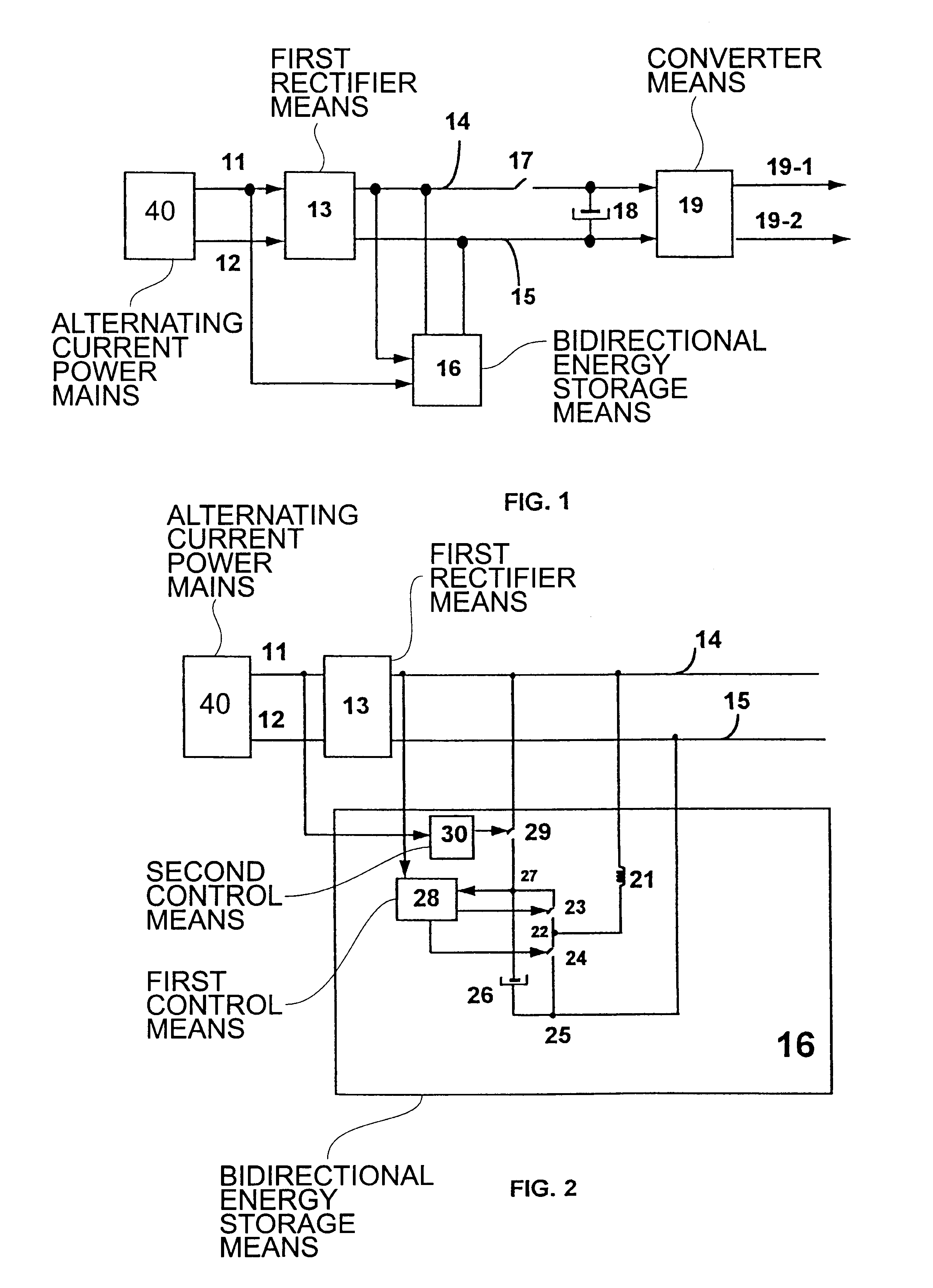
FIG. 1 is a simplified block diagram of a preferred embodiment of the switched power converter with hold-up time and harmonics reduction, comprising input terminals 11 and 12 connected to an alternating current (AC) power mains 40 for supplying power to a first rectifier means 13, for example a full-wave diode rectifier, that produces at its output a rectified sine wave voltage.

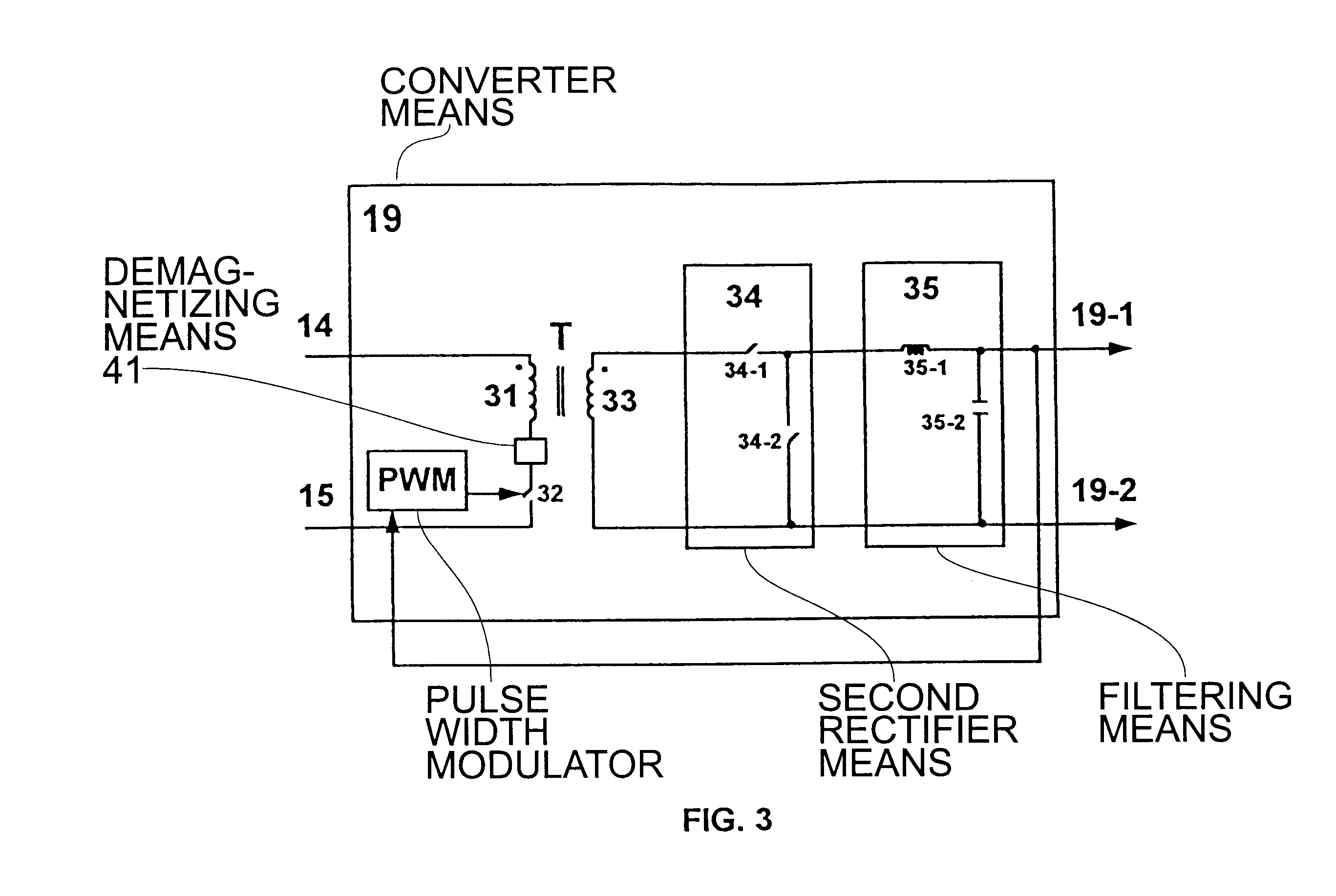
The output of the first rectifier means 13 is connected by means of conductors 14 and 15 to the input of at least one converter means 19 for producing at least one regulated DC voltage across its output terminals 19-1 and 19-2, said voltage being applied to a load.

A first switching device 17 is situated between the first rectifier 13 and the converter means 19 on the conductor 14. The first switching device 17 can have a control terminal by which its on and off states, conducting and nonconducting periods, respectively, are controlled.

Across the conductors 14 and 15, and before the first switching device 17, ...


PUM


Abstract

Switched power converter with hold-up time and harmonics reduction connected to an AC power mains through a first rectifier means (13) and connected to conversion means (19) supplying a regulated voltage.An energy storage means (16) connected in parallel with the rectifier means (13), absorbs or supplies current to the conversion means (19), by adapting the conducting periods of two switching devices in such a way that determines the voltage level on the storage means (16) and assures a sinusoidal current at input terminals (11, 12).The two switching devices are switched in a complementary manner by means of a first control means included in the energy storage means (16).

Description

OBJECT OF THE INVENTIONThe present invention relates to a switched power converter which is connected to an alternating current (AC) power mains for rectifying the received voltage sine wave and converting it to a voltage level suitable for feeding to at least one load, such as a telecommunications equipment.For performing the conversion switching elements are employed which are switched at high frequency and, as a result, generate harmonics in the input current, possibly producing distortion that interferes with the normal operation of other devices connected to the AC power mains.Known techniques, as power factor correction, are used to reduce the harmonics content in the input current, by approximating the input current waveform to a sinusoid, said power factor correction circuits being in general complex.STATE OF THE ARTAt the present time a switched power converter is known for maintaining a high power factor at its input terminals from the U.S. Pat. No. 4,903,181, being incorp...

Claims


Application Information

Patent Timeline
Patent Type & Authority Patents(United States)
IPC IPC(8): H02M1/00H02M7/12H02M1/42H02M3/28
CPCH02M1/4208Y02B70/126H02M2001/0096Y02B70/10H02M1/0096
Inventor TARODO, ANTONIO FONTANDE LA CRUZ MORENO, ENRIQUEVELASCO, SALVADOR OLLERO
Owner ALCATEL LUCENT SAS
Why Eureka
Try Eureka