
Speculum

Inactive Publication Date: 2001-08-28
SURGONOMICS
View PDF11 Cites 74 Cited by
  • Summary
  • Abstract
  • Description
  • Claims
  • Application Information

AI Technical Summary

Benefits of technology

It is thus an object of the present invention to provide a speculum which provides greater patient comfort, is easier to use by the health care provider, can be modified for different sizes of body cavities, is simplistic in design and can be manufactured at a reasonable cost.
It is yet another aspect of the present invention to provide a speculum with an optional smoke evacuator and fiber-optics light source. Blades with built-in smoke evacuators as well as fiber-optic light sources will improve visualization and safety for electrosurgical procedures. These components can be easily and quickly added to one or more blades in different positions as the clinical situation dictates.

Problems solved by technology

Most apparently, its basic design is uncomfortable to the patient, and frequently elicits anxiety and apprehension toward the vaginal exam.
The broad, flattened orientation of the blades does not respect the oval contour of the vaginal vault, and its insertion is often uncomfortable or painful to the patient.
This is an uncomfortable situation for the healthy patient and often a desperate one for the patient with a bladder or urethra complication.
Common complaints additionally include the sensation of a cold metal tool being placed in the vagina, or simply the difficulties met with its insertion.
From the health care provider's perspective, the tool's objective of providing visualization of the cervix is far from optimal.
A vicious cycle then ensues with the prior art design.
This naturally causes great discomfort for the patient and frustration for the care provider.
The former method is sub-adequate as it severely limits visualization, mobility and speculum expansion.
The latter method is impractical, expensive, and crowds two tools into an already limited work space.
Further, since the typical speculum is only applicable in a minimum number of sizes without interchangeable blades, it is not readily adapted to be used with a variety of different patients and anatomies associated therewith.
Conventional speculum designs not only limit visualization of the cervix, but frequently induces tissue trauma.
With friable or inflamed tissue this immediately causes bleeding and pain, further compromising the exam.
Thus, the cervix and vagina are often poorly visualized and sampled, compromising the screening, diagnosis, and treatment of genital pathology.
Unfortunately, the device is difficult to open based on the mechanics of the opening mechanism, has blade tips which are too large, thus causing pain and discomfort in many patients.
Further, the Examining "window" is inherently small due to the design and the handle is inconveniently located directly behind the longitudinal axis of the blades.

Method used


Image

  • Speculum
  • Speculum
  • Speculum

Examples


Embodiment Construction

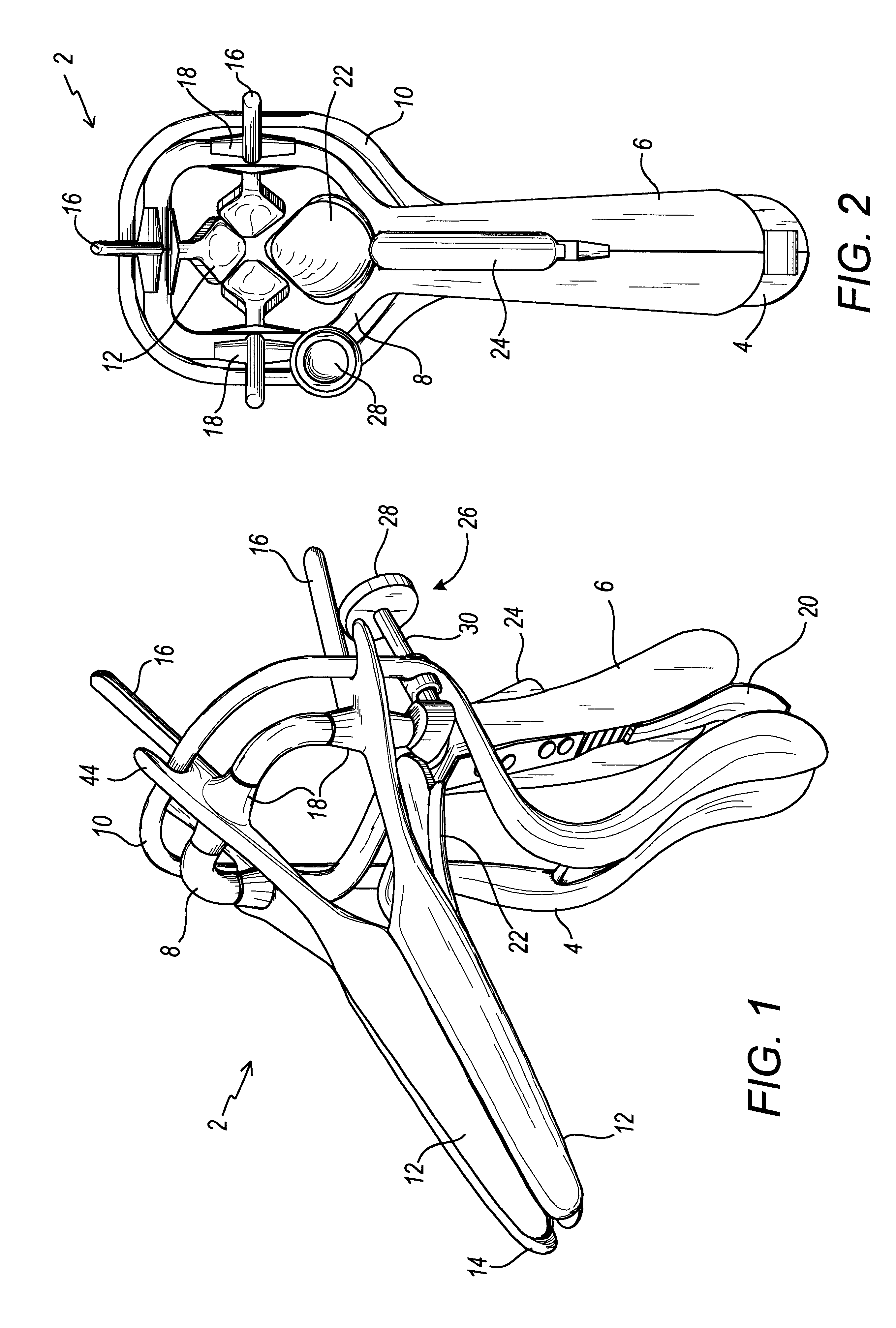
Referring now to the drawings, FIG. 1 is a left perspective view of the speculum 2 of the present invention. FIG. 2 is a rear elevation view, while FIG. 3 is a left elevation view of the speculum 2 shown in FIG. 1. In general, the speculum 2 is comprised of a forward handle 4 which is interconnected to a rearward handle 6 with a biasing spring 20. The biasing spring serves to keep the forward handle 4 and rearward handle 6 in a spaced apart relationship when not in use. In this position of non-use, the front ends 14 of the blades 12 are oriented in a closed position. On the upper end of the forward handle 4 is a traveling ring 10 which serves to open a plurality of pivoting blades 12 as will be discussed in greater detail below. The rearward handle 6 is interconnected to a stationary ring 8 on the upper portion which serves to support the plurality of pivoting blades 12.

The pivoting blades 12 generally have a front end 14, a hook end 16 and a blade sleeve 18 positioned therebetween....


PUM


Abstract

A speculum is provided for examining a body cavity by the use of a one handed, simplistic design which improves visualization, is more comfortable to the patient and which can be manufactured in a cost effective manner.

Description

FIELD OF THE INVENTIONThe present invention relates to hand-held medical devices, and more specifically speculums used for examining body cavities.BACKGROUND OF THE INVENTIONThe vaginal speculum is a device which has long been used to visualize the cervix and vaginal walls, as well as to gain trans-cervical access to the uterus. The mechanics of a typical speculum are based on a simple design, one which articulates two "blades" on a handle to expand the vaginal walls in an anterior-posterior, or "front to back" orientation. For years this design has provided adequate exposure and visualization for examining physicians, and allowing for the diagnosis and treatment of vaginal, cervical and endometrial disorders.Any health care provider familiar with the design and operation of a typical speculum has at one or more times been made aware of its limitations. Most apparently, its basic design is uncomfortable to the patient, and frequently elicits anxiety and apprehension toward the vagin...

Claims


Application Information

Patent Timeline
IPC IPC(8): A61B1/32
CPCA61B1/32A61B1/06
Inventor RESNICK, SCOTT
Owner SURGONOMICS
Learn More