
Composition for use in making optical components

Inactive Publication Date: 2001-07-17
PHYSICAL OPTICS CORP
View PDF15 Cites 26 Cited by
  • Summary
  • Abstract
  • Description
  • Claims
  • Application Information

AI Technical Summary

Benefits of technology

A primary object of the invention is to provide an apparatus for producing replicas of a surface topography with enhanced overall cost effectiveness. It is another object of the invention is to provide an apparatus that is rugged and reliable, thereby decreasing down time and operating costs. It is yet another object of the invention is to provide an apparatus that has one or more of the characteristics discussed above but which is relatively simple to operate using a minimum of equipment and relatively simple to setup and operate using relatively low skilled workers.
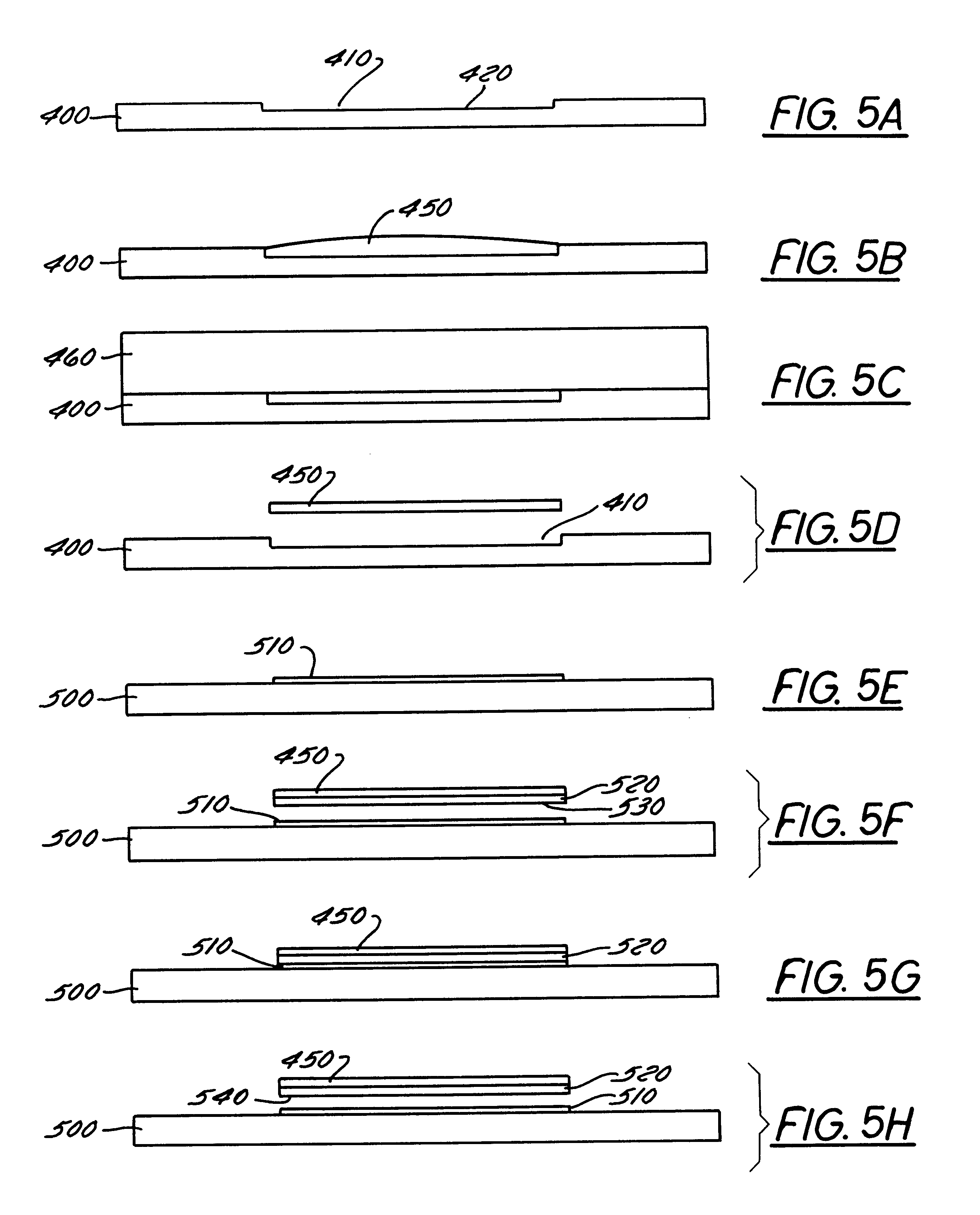
Another object of the invention is to provide a method of producing replicas of optical elements that are to be embedded in an optical component. It is another object of the invention to provide a method that is predictable and reproducible, thereby decreasing variance and operating costs. It is yet another object of the invention to provide a method that has one or more of the characteristics discussed above but which is relatively simple to practice using relatively low skilled workers.

Problems solved by technology

In the past, this replication process has been inefficient because the replicas were made individually.
Thus, a previously recognized problem has been that large amounts of time are consumed in making a large number of replicas, resulting in a high per unit cost which did not decrease as the number of replicas made increased.
However, merely enhancing the efficiency of the replication step without considering any attendant increase in overall costs is not an adequate solution because the way in which the replication step is improved may involve more time, expense and / or energy than is saved due to improvements in the replication step.
For example, one unsatisfactory previous approach involves machining the master topography into an outer surface of a cylindrical unitary metal drum.
However, a disadvantage of this previously recognized approach is that such a metal drum is a single purpose tool.
When there is no longer any demand for a particular replica, the metal drum cannot be adapted for another use because the master topography is an integral part of the drum itself.
Moreover, this previously recognized solution also has the significant disadvantage of high initial cost.
From a business point of view, the decision of whether or not to invest in such a unitary metal drum can be problematic where the individual orders in-hand for a particular type of replica do not justify the cost of machining a unitary metal drum.
A previously recognized problem has been that the light from the backlight must be polarized in order for the LCD to function properly.
However, a major disadvantage of this approach is that a large amount of the available light from the backlight is not transmitted through the polarizing sheet, thereby resulting in decreased brightness.
However, this approach has the significant disadvantage of relatively high cost.
Specifically, the cost of providing the optical elements on the bottom surface of the backlight is too high.
For example, injection molding such a backlight requires expensive tooling and several minutes of production time for each molding.
Further, the cost of tooling is even higher where a large number of optical elements are to be formed on each backlight or where the size of each of the optical elements is small.
Heretofore the above-discussed requirements have not been fully met.

Method used


Image

  • Composition for use in making optical components
  • Composition for use in making optical components
  • Composition for use in making optical components

Examples


Embodiment Construction

The present invention and the various features and advantageous details thereof are explained more fully with reference to the nonlimiting embodiments described in detail in the following description.

1. System Overview

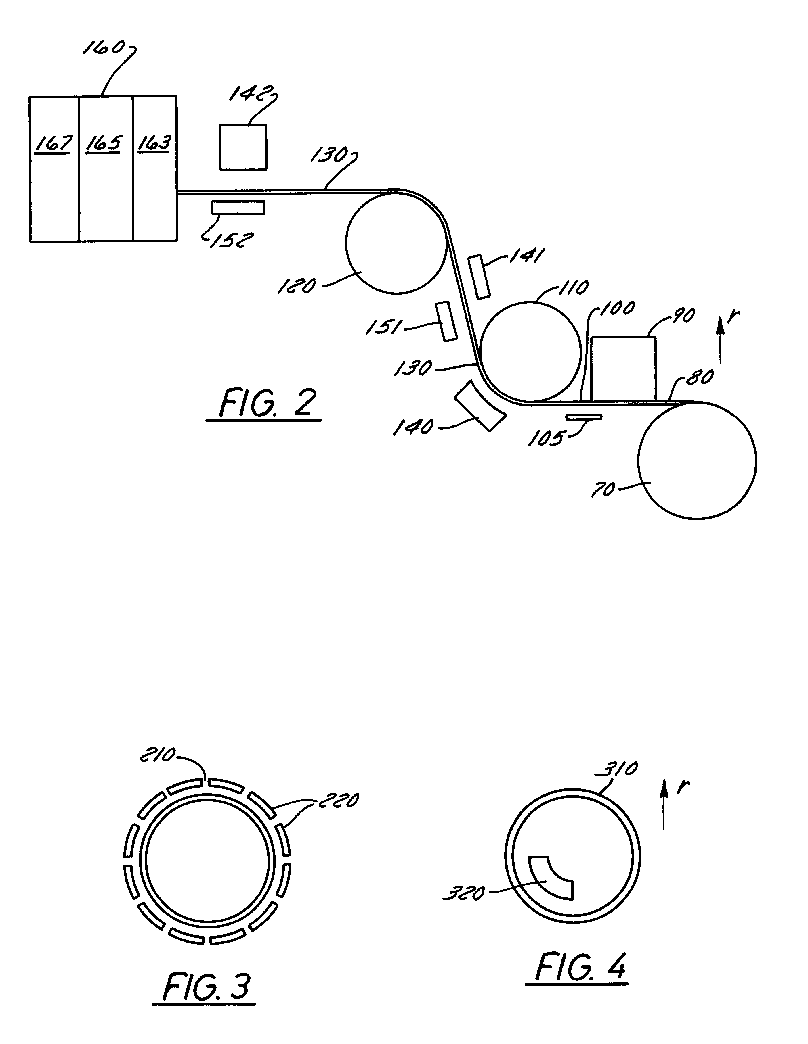
The above-mentioned requirements are mutually contradicting and cannot be satisfied simultaneously in the case of a machined cylindrical unitary metal drum. However, it is rendered possible to simultaneously satisfy these requirements to a certain extent by employing a drum that includes a plurality of submasters in consideration of the fact that the submasters can themselves be replicas.

2. Detailed Description of Preferred Embodiments

Referring to the drawings, especially FIGS. 2-4, it can be seen that a surface topography can be replicated on a continuous basis using a drum that includes a plurality of submasters. Pursuant to the present invention, complex surface topographies that include a large number of very small features can be efficiently replicated and then em...


PUM

PropertyMeasurementUnit
Fractionaaaaaaaaaa

Abstract

Compositions for producing replicated optical components are disclosed. A composition for making a large scale submaster optical component includes a mixture having an acrylated aliphatic urethane oligomer / monomer blend and a tripropylene glycol diacrylate. The mixture is combined with a number of other components including an isobornyl acrylate, an ultraviolet polymerizing varnish, a surfactant, and a photoinitiator. A composition for making a large scale replica optical component includes a mixture having an acrylated aliphatic urethane oligomer / monomer blend and a tripropylene glycol diacrylate. The mixture is combined with an isobornyl acrylate, a beta-Carboxyethyl acrylate, a photoinitiator, and an N-vinyl-2-pyrrolidone. A composition for making a small scale submaster optical component includes an ultraviolet polymarizing varnish and a surfactant.

Description

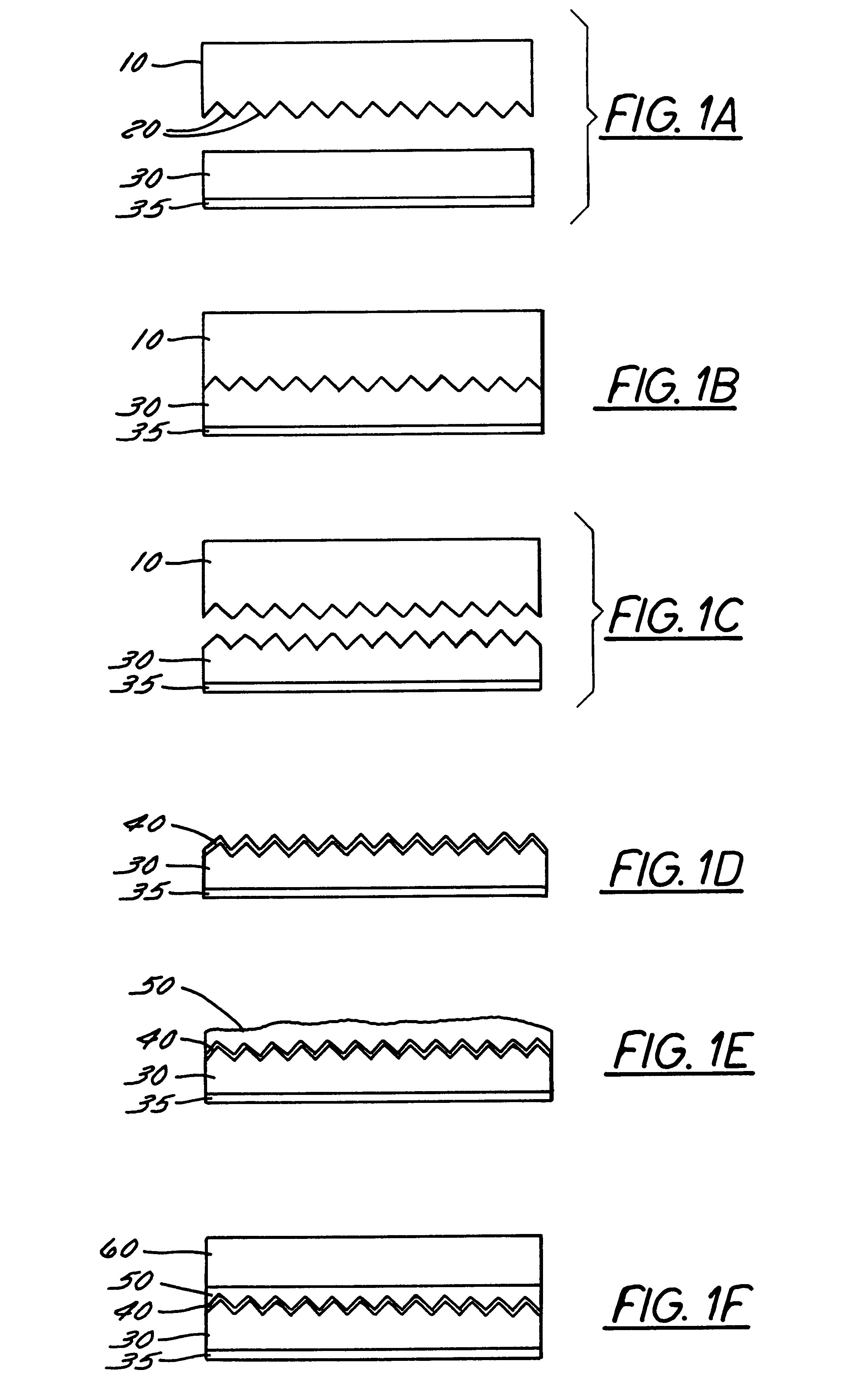
1. Field of the InventionThe present invention relates in general to the field of making laminated components. More particularly, the present invention relates to a method of making laminated optical components having embedded optical elements. Specifically, a preferred embodiment of the present invention relates to a method of making the collimating backlight of a liquid crystal display system by replicating a plurality of optical elements in a layer of material and then laminating the replication side of the layer to a substrate with an index of refraction matching material, thereby embedding the optical elements within the collimating backlight. The present invention thus relates to a method of making optical components of the type that can be termed lamination embedding.2. Discussion of the Related ArtWithin this application several publications are referenced by arabic numerals within parentheses. Full citations for these, and other, publications may be found at the end of the ...

Claims


Application Information

Patent Timeline
IPC IPC(8): B29C41/00B29C41/26B29D11/00F21V8/00G02B5/04G02B6/122B29C39/10B29C39/24G02B5/02C08F2/50
CPCB29C41/26B29D11/0073G02B6/1221G02B6/0033G02B6/0065G02B5/045
Inventor SAVANT, GAJENDRALATCHINIAN, HAGOP
Owner PHYSICAL OPTICS CORP
Learn More