
Trailer tire pressure-monitoring system

a technology of tire pressure monitoring and trailer tires, which is applied in the direction of tire measurement, vehicle components, transportation and packaging, etc., can solve the problems of system prone to erroneous readings, damage to trailers as well as collateral damage to other motorists, and damage to trailers. , to achieve the effect of convenient use and convenient installation

Inactive Publication Date: 2001-06-12
ANDSAGER RICHARD L
View PDF6 Cites 39 Cited by
  • Summary
  • Abstract
  • Description
  • Claims
  • Application Information

AI Technical Summary

Benefits of technology

A primary object of the present invention is to fulfill the above-mentioned need by the provision of a trailer tire pressure monitoring system. A further primary object of the present invention is to provide such a system which is efficient, inexpensive, easy to use, and easy to install. In addition, it is a primary object of the present invention to provide such a system which can differentiate between relative changes in tire conditions due to vehicle-turning versus changes in tire conditions due to actual air pressure loss.
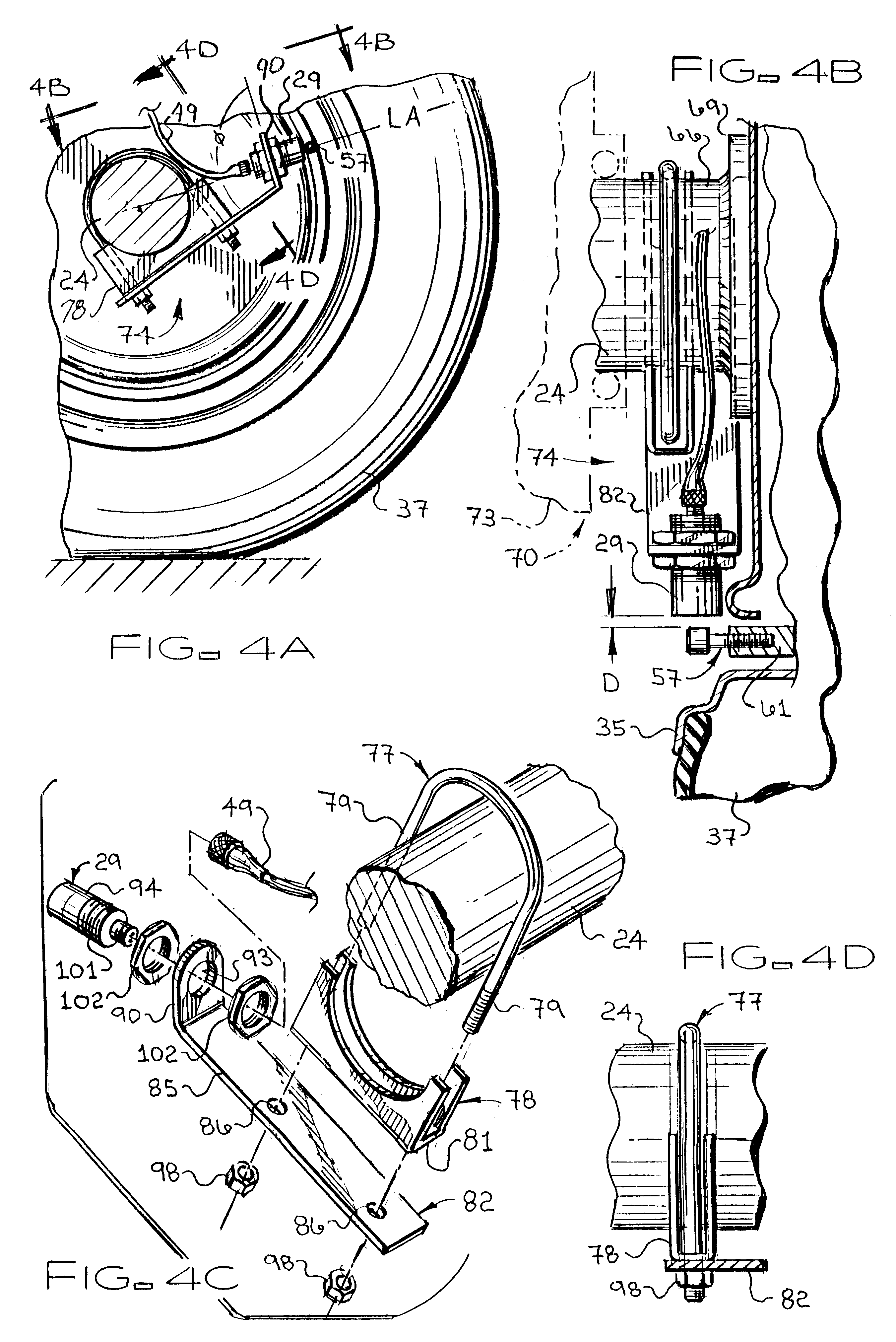
Also, this invention provides such system further comprising: a tow vehicle of a type adapted to attach to such trailer; and an alarm indicator attached to such tow vehicle, such alarm indicator being constructed and arranged for coupling to the computer in such manner as to provide an indication of an abnormal rotational speed of a such wheel. It also provides such system wherein each sensor is non-rotatably attached to an axle of such trailer; and, further, wherein each sensor is a proximity sensor. This invention also provides such a system wherein each target comprises a protuberance extending from and rotatably attached with one wheel; and also, wherein each such protuberance is connected to a brake drum of one wheel. Further still, this invention provides such system further comprising a programming means for programming the computer for counting rotations of each of a plurality of wheels of the trailer within the same fixed time period in such manner as to provide less sensitivity to rotational-count differences at lower trailer speeds.
In addition, this invention also provides a method of installing a low tire pressure alarm system for sensing abnormal rotational speeds of a plurality of wheels on a trailer adapted for coupling to a tow vehicle, comprising the steps of: providing a plurality of metal targets and a trailer having at least two wheels; preparing each such wheel with first attachment means for attaching a target to each wheel in such manner that the target rotates with the wheel; mounting each target on a wheel in such manner as to provide a sensing target rotating with the wheel; providing a plurality of proximity sensors; preparing an axle area adjacent each wheel with a second attachment means for attaching one proximity sensor; mounting each proximity sensor non-rotatably to the trailer in such manner as to sense rotations of one target past one proximity sensor and to generate signals representing rotational speeds of the wheel; providing a computer structured and arranged so as to receive signals from each proximity sensor and to use such signals to compare representations of rotational speeds of the wheels; mounting the computer on the trailer and coupling the computer to each proximity sensor; and mounting on the trailer a trailer coupler constructed and arranged to assist in system coupling of the computer to an alarm indicator within a tow vehicle of a type adapted to attach to a trailer. In addition, this invention provides such method further comprising the steps of: providing a tow vehicle of a type adapted to attach to a trailer; providing an alarm indicator constructed and arranged for coupling to a computer in such manner as to provide an indication of an abnormal rotational speed of a wheel; and mounting an alarm indicator within a cab of such tow vehicle. It also provides such method wherein each proximity sensor is non-rotatably attached to an axle of such trailer; as well as wherein each target comprises a protuberance extending from and rotatably attached with one wheel. It further provides such method wherein each protuberance is connected to a brake drum of one wheel, and wherein the computer does such comparing essentially by counting differences in number of rotations of each wheel; and, also, further comprising the step of using a programming means for programming the computer for counting rotations of such wheels of such trailer within the same fixed time period in such manner as to provide less sensitivity to rotational-count differences at lower trailer speeds.

Problems solved by technology

For single axle trailers comprising only one tire on each side of the trailer, a failure in a single tire may lead to catastrophic consequences, such as trailer rollover or jackknifing, which may not only damage the contents of the trailer but also produce a traffic hazard to other motorists.
Even for those single-axle trailers having dual wheels per trailer side, or multi-axle trailers comprising multiple wheels on each side of the trailer, a single tire failure can still result in damage to the trailer as well as collateral damage to other motorists caused by flying tire debris.
Although this system may be adequate for its intended uses despite certain inefficiencies, the fact that signals are sent to the central receiver unit via an electromagnetic path makes this system susceptible to erroneous readings when used on a trailer due to the fact that trailers are often equipped with electric brakes which also generate magnetic fields.
Although such systems also may be adequate for their respective intended uses, the fact that trailers typically are not provided with ABS or TRC hardware makes the aforementioned prior art systems unsuited for trailer applications.
Thus, the aforementioned systems and associated methods for monitoring tire pressure for passenger vehicles do not adequately address nor solve the above concerns with respect to trailers.

Method used


Image

  • Trailer tire pressure-monitoring system
  • Trailer tire pressure-monitoring system
  • Trailer tire pressure-monitoring system

Examples


Embodiment Construction

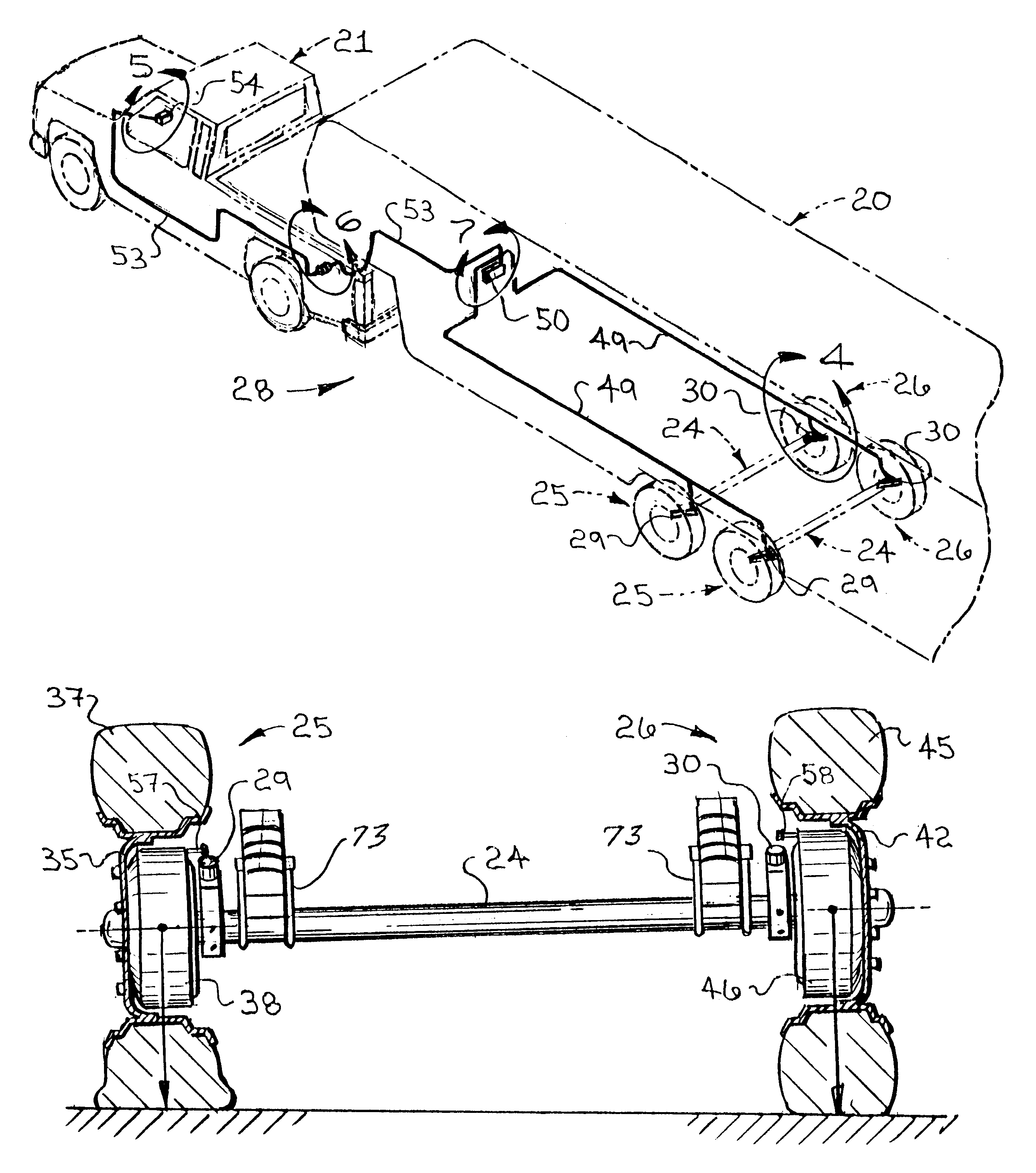
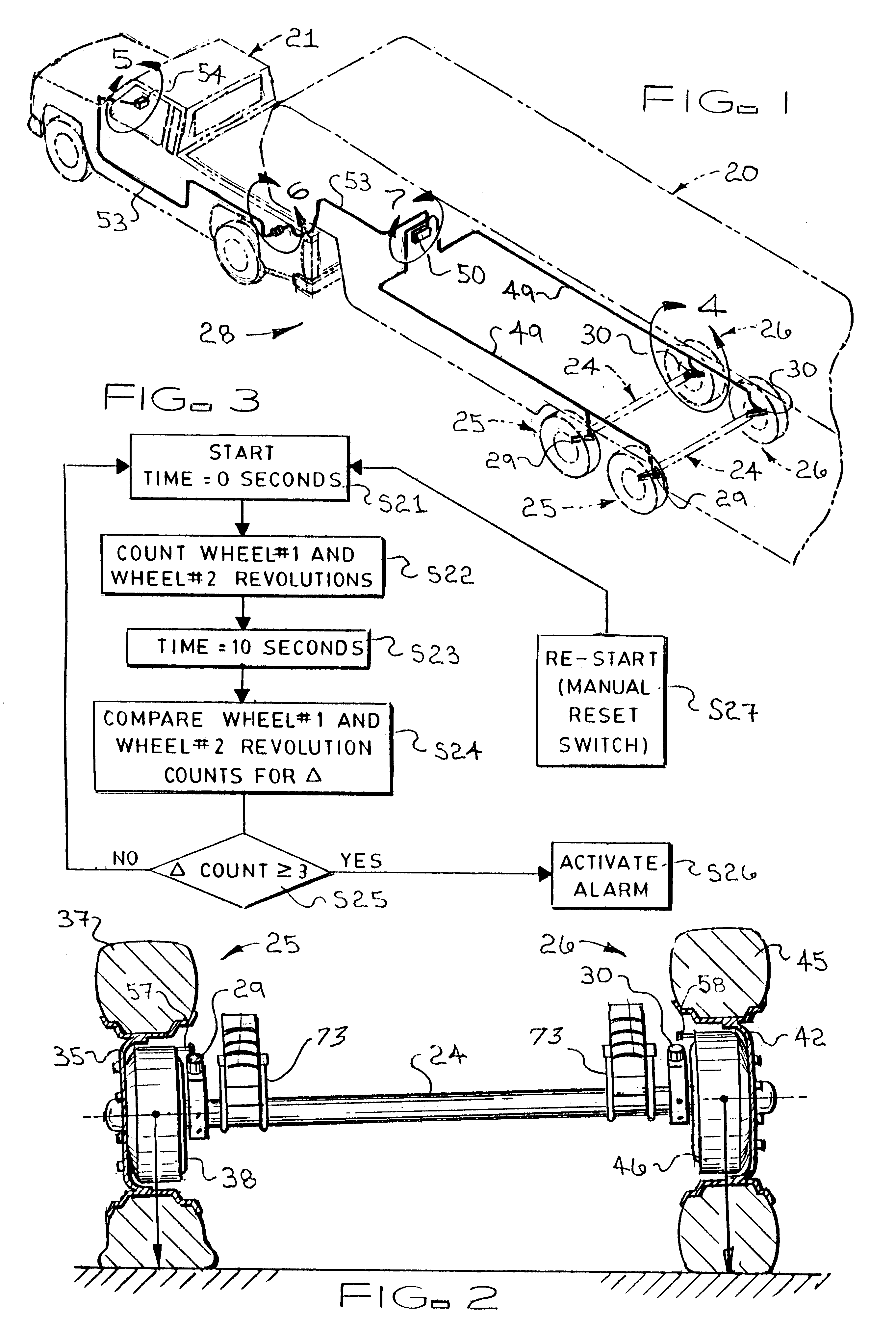
Referring now to the Figures, shown in perspective (in dotted lines) in FIG. 1 is a trailer 20 coupled, in well-known ways, to tow vehicle 21. For example purposes only, trailer 20 is shown comprising a dual-axle arrangement with the arrangement shown being embodied by axles 24 having attached left and right wheel arrangements 25 and 26, respectively. Although a dual-axle arrangement is shown, it is to be understood that the trailer tire pressure-monitoring system (herein monitoring system 28) of the present invention may be effectively used with those trailers 20 comprising axles 24 numbering one or more. As will be appreciated by those skilled in such art, the monitoring system 28 of the present invention effectively ascertains when an abnormal tire condition is present on the trailer 20 and alerts the driver of this condition while there is time to correct the condition prior to catastrophic failure.

Though the details of the monitoring system 28 of the present invention will be d...


PUM


Abstract

A tire pressure-monitoring system for use with a trailer. The monitoring system includes an inductive proximity sensor mounted adjacent each wheel. To activate the sensors, a target is mounted on each brake drum. Rotational speed data for each wheel is relayed from each sensor to a programmable logic controller which compares the rotational speed of a wheel with another wheel. Sensitivity parameters written into the program contained in the programmable logic controller compares the input data and, if the data falls outside the safe parameters, alerts the driver by activating and audio or visual alarm mounted within the tow vehicle. The sensitivity of the programmed logic may be optimized to differentiate changes in a tire diameter due to turning versus an actual loss in tire pressure.

Description

1. Field of the InventionThis invention relates to providing a trailer tire pressure monitoring system. More particularly, this invention concerns a trailer tire pressure monitoring system for warning the driver of a deflating tire on a trailer prior to tire failure. In addition, this invention concerns the provision of a tire pressure monitoring system which is capable of detecting a deflated tire by comparing the rotational speed of several tires.2. Description of the Prior ArtTypically, vehicle-coupled trailers are used to transport an assortment of cargos such as, for example, goods, livestock, and transient living quarters. Oftentimes, the driver of the towing vehicle will be unaware of the occurrence of air pressure loss in one or more of the trailers tires until it is too late and the tire fails. For single axle trailers comprising only one tire on each side of the trailer, a failure in a single tire may lead to catastrophic consequences, such as trailer rollover or jackknifi...

Claims


Application Information

Patent Timeline
Patent Type & Authority Patents(United States)
IPC IPC(8): B60C23/06
CPCB60C23/061
Inventor ANDSAGER, RICHARD L.
Owner ANDSAGER RICHARD L
Learn More