Shaping frame

Inactive Publication Date: 2001-06-05
WILH WISSNER GMBH
View PDF29 Cites 25 Cited by
  • Summary
  • Abstract
  • Description
  • Claims
  • Application Information

AI Technical Summary

Benefits of technology

In contrast to a shaping frame made of memory metal, the shaping frame according to the invention may be produced relatively cost-effectively from wire or plastic, has a higher level of dimensional stability than the frame made of memory metal and, in relation to the known shaping frames consisting of wire, has the advantage that, with a comparatively high level of rigidity in the frame plane, ensures a high level of flexibility in the direction perpendicular to the frame plane. In particular, the relatively frequently occurring breakages of the known wire frames on account of the bending loading in the frame plane occur less frequently since the shaping frame according to the invention, on the one hand, easily bends out in the direction perpendicular to the frame plane in the case of excessive bending loading in the frame plane, and the high bending stressing of purely bending loading is reduced by bending / torsional loading being caused at the same time, and, on the other hand, along with the same level of flexibility in the direction perpendicular to the frame plane, it is possible to select a larger overall cross section.
If required, it is also possible to position three or more frame elements in layers. This may be desirable, for example, when the rigidity in the frame plane is increased further and, at the same time, the flexibility in the direction perpendicular to the frame plane is not to be adversely affected, which would be the case if there were an increase in merely the width of a two frame elements in the direction perpendicular to the frame plane. If more than two frame elements are used, then the planes of the in this case at least two separating surfaces are located in an essentially parallel, offset arrangement in relation to the central frame plane.
The overall cross section of the shaping frame according to the invention, essentially comprising the sum of the individual cross sections of the frame elements, preferably has a long cross-sectional axis and a short crosssectional axis, the long cross-sectional axis being located essentially in the frame plane. The overall cross section may be, for example, rectangular, elliptical, C-shaped or I-shaped. However, a circular overall cross section is also conceivable since such a cross section, with the configuration according to the invention, also effects the desired increase in flexibility in the direction perpendicular to the frame plane.
If the frame elements are not fastened on one another or retained on one another by specifically provided retaining or guide devices, then this function is performed by the frame channel which is provided on the item of clothing for supporting a woman's bust and which is intended for receiving the shaping frame according to the invention and / or by a material frame strip into which the shaping frame is pushed. Should it be desired, however, for the frame elements to be retained on one another, then it is possible to provide a rivet-like guide with play, which allows relative movement of the frame elements in relation to one another in the frame plane.

Problems solved by technology

The round-wire shaping frames known from the prior art do not fully satisfy these requirements since they have a relatively high level of rigidity in the direction perpendicular to the frame plane.
This adversely affects, on the one hand, the wearing comfort and, on the other hand, the geometry of the ends of the shaping frames, which are relatively high in relation to their width, with the result that the operation of rounding off their sharp edges in order to protect the fabric of the item of clothing can only be carried out with relatively high outlay.
There is also the problem here that it is not possible to reduce as desired the width of the cross section perpendicularly to the frame plane in order to achieve the highest possible level of flexibility in this direction.
However, these frames also have a considerably lower level of rigidity in the frame plane and, moreover, memory metals cost so much as to preclude cost-effective production of shaping frame using these materials.

Method used


Image

  • Shaping frame
  • Shaping frame
  • Shaping frame

Examples


Embodiment Construction

a) Technical Object

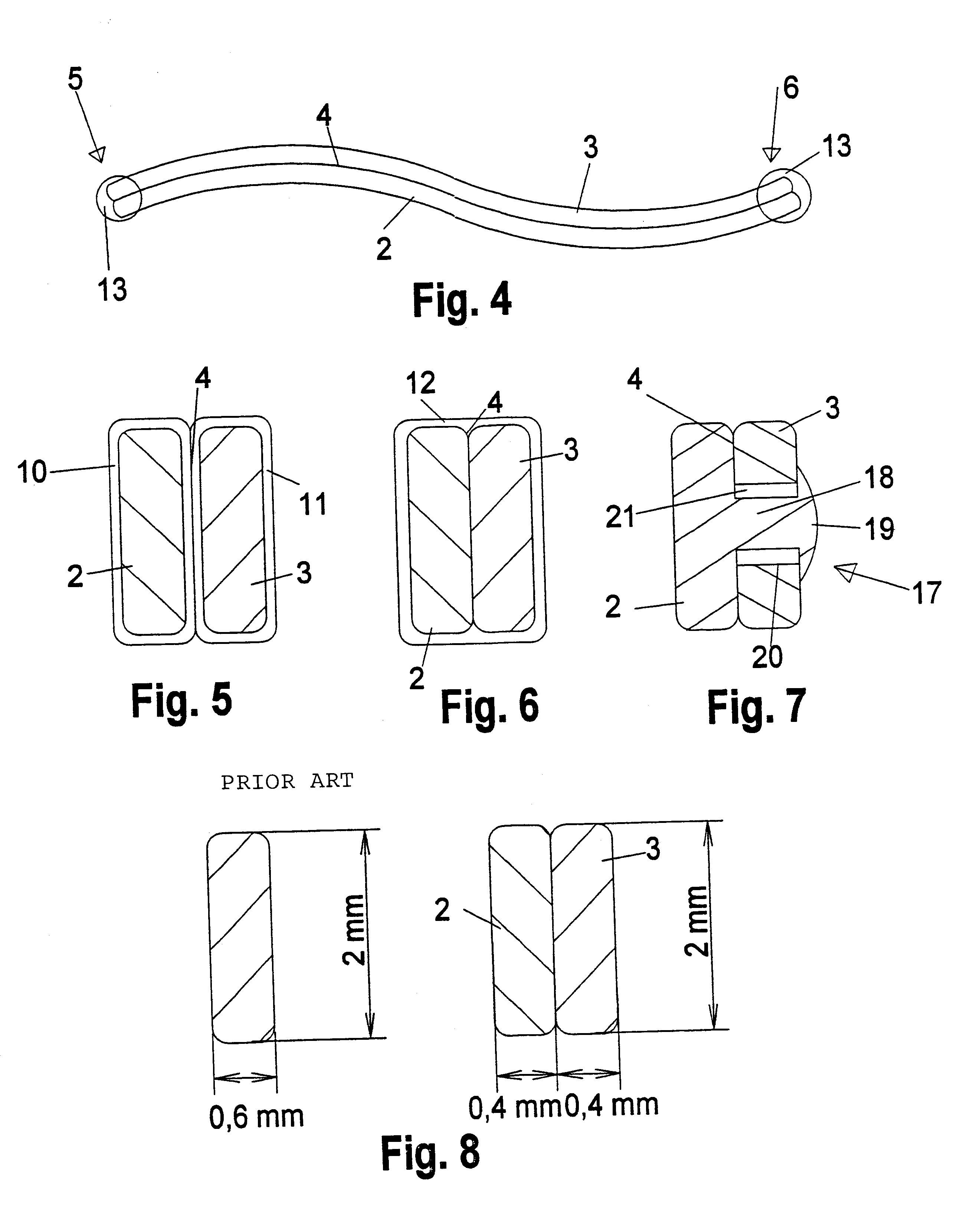
The object of the present invention is thus to provide a shaping frame which is intended for items of clothing supporting a woman's bust, and an item of clothing for supporting a woman's bust, said frame and item of clothing ensuring the highest possible level of rigidity in the frame plane and the highest possible level of flexibility in the direction perpendicular to the frame plane and, at the same time, being capable of being produced as cost-effectively as possible.

b) Achieving the Object

This object is achieved by means of a shaping frame and of an item of clothing according to claims 1 and 19, respectively. Further configurations of the invention can be gathered from the subcdaims.

The invention proposes to configure a shaping frame, which is intended for items of clothing supporting a woman's bust, such that the frame comprises at least two frame elements which are arranged essentially one behind the other in the direction perpendicular to the plane defined ...


PUM


Abstract

The invention relates to a shaping insert (1) for garments for supporting a woman's bust. The aim of the invention is to provide as much bend resistance as possible in the plane stressed by the insert and as much flexibility as possible in relation to bending stresses perpendicular thereto. At the same time, the insert should be as economical as possible to produce. To this end, the insert is configured with at least two insert elements (2, 3) which are arranged essentially one behind the other in the direction perpendicular to the plane which is stressed by the insert. The two insert elements are curved essentially identically either side of the bottom of the insert.

Description

I. APPLICATION AREAThe invention relates to a shaping frame which is intended for items of clothing supporting a woman's bust, and to an item of clothing for supporting a woman's bust.II. TECHNICAL BACKGROUNDSuch shaping frame usually consist of bent wire and are worked into the cups of corsetry, e.g. of bras, bikini tops, bustiers, etc. They retain the fabric of the corsetry in a dimensionally stable manner against the wearer's body even under mechanical loading, e.g. when the wearer is walking, and thus ensure a reliable fit and a well-shaped bust.In mechanical terms, the shaping frame have to meet various requirements. On the one hand, they are to have the highest possible bending strength in relation to bending resulting from forces which occur in the plane defined by the bent frame (frame plane). On the other hand, they are to be as pliable and / or flexible as possible in relation to bending resulting from forces acting perpendicularly to the frame plane. Finally, a further requ...

Claims


Application Information

Patent Timeline
IPC IPC(8): A41C3/00A41C3/12
CPCA41C3/122A41C3/126A41C3/128
Inventor HOFER, ULRICH
Owner WILH WISSNER GMBH
Why Eureka
Try Eureka