Plant cultivation mat
- Summary
- Abstract
- Description
- Claims
- Application Information
AI Technical Summary
Problems solved by technology
Method used
Image
Examples
first embodiment
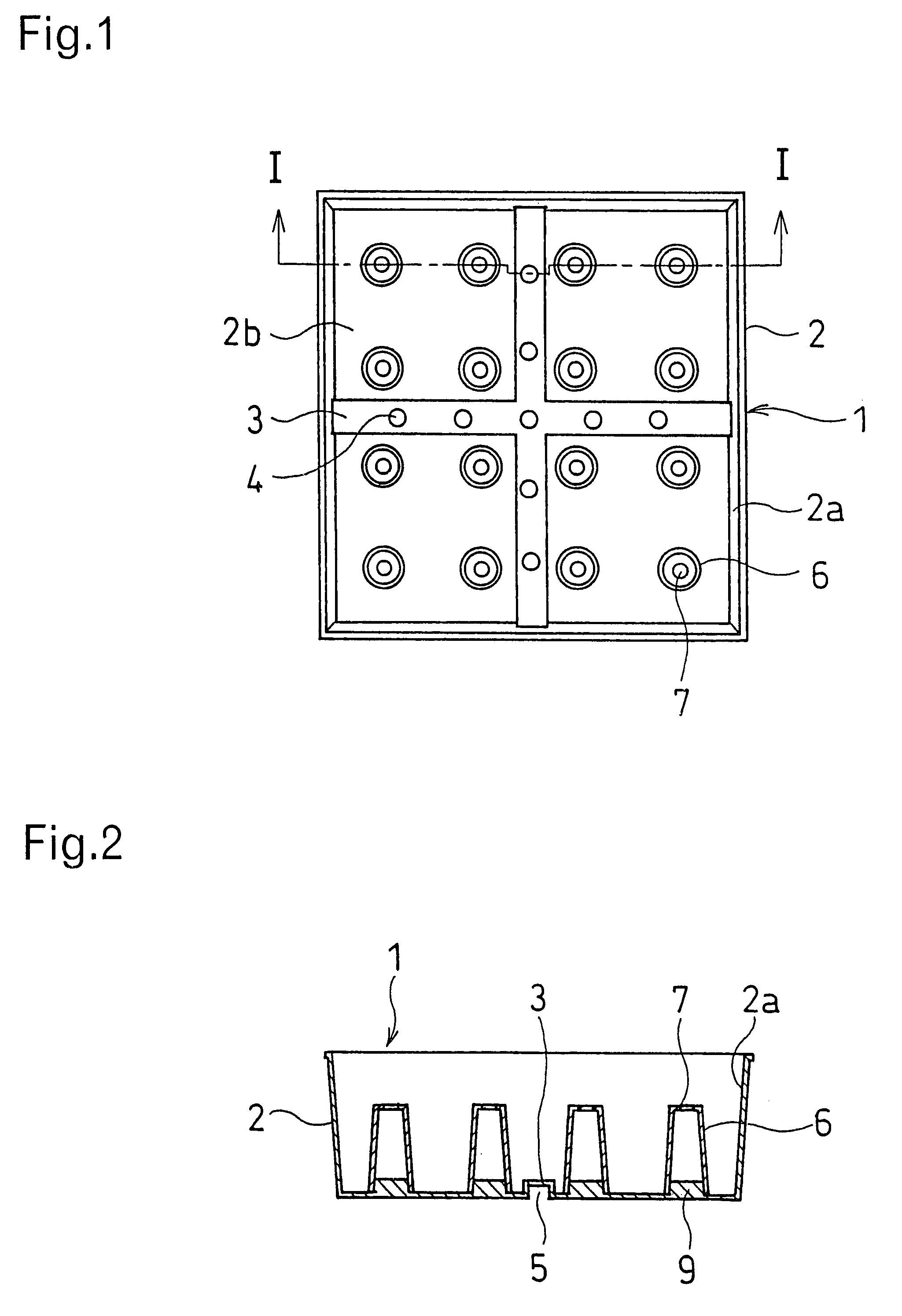
Referring first to FIGS. 1 and 2, showing the plant cultivation mat according to the present invention, the mat 1 is composed of a cell 2 disposed in a recessed form with its top part being open upward. The lateral wall 2a of the cell 2 is tapered downward from its top to bottom, forming an inwardly tapered face.
In the bottom part 2b of the cell 2, there are formed protruded parts (or ribs) 3 in both vertical and horizontal directions, and water-passage ports 4 are perforated in the top surface of the protruded parts (ribs) 3 at their predetermined location. The inside of the protruded part 3 forms a space in an inverted U-shape to constitute a concaved groove (opening) 5 to cause excessive water to be drained through this concaved groove 5.
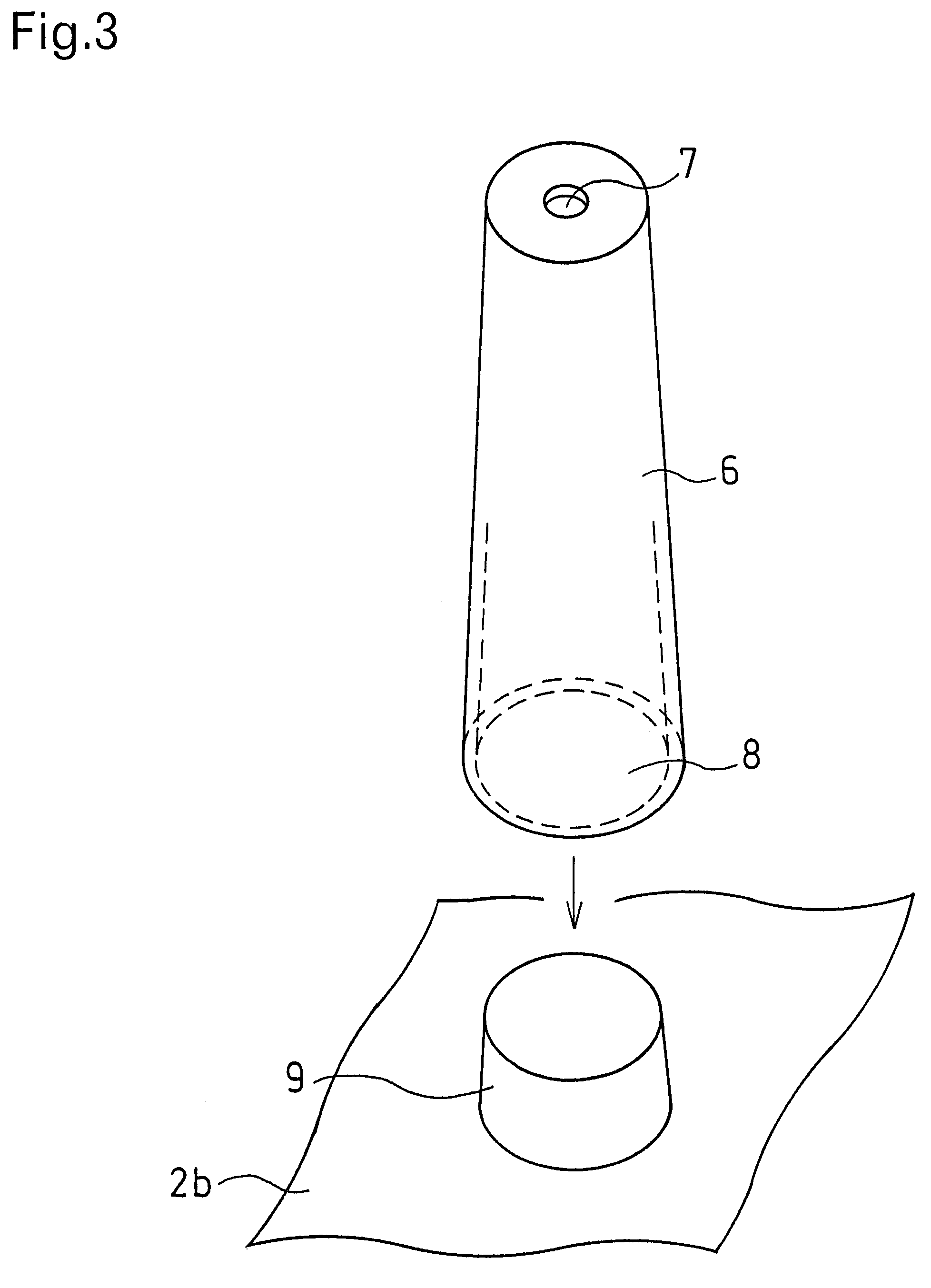
In a region defined by the protruded part 3 and the lateral wall 2a of the cell 2, there are fixed in the upright position four pillar members 6 with respect to the bottom part 2a of the cell 2, each pillar member being independent of the others....
second embodiment
FIGS. 4 and 5 illustrate the plant cultivation mat 1 according to the present invention, This plant cultivation mat 1 consists of a single cell 2 which is disposed in a recessed form, with the lower part of the lateral walls 2a on all four sides being indented inwardly to form an indentation 10.
A raised part (or rib) 3 is formed on the bottom part of the lateral wall 2a of the cell 2, extending toward the center of the bottom face 2b, and a water-passage port 4 is perforated in the upper end surface of the raised part 3 situated near the center of the cell 2. The inside of the raised part 3 forms a space in the form of an inverted U, thus constituting an open part 5 of the recessed groove. Excessive water being discharged from this water-passage port 4 through this opening 5.
Between the adjacent raised parts 3 and the lateral walls 2a of the cell 2, there are erected four independent pillar members 6, a small hole 7 being perforated in the top surface of each of the pillar members. ...
third embodiment
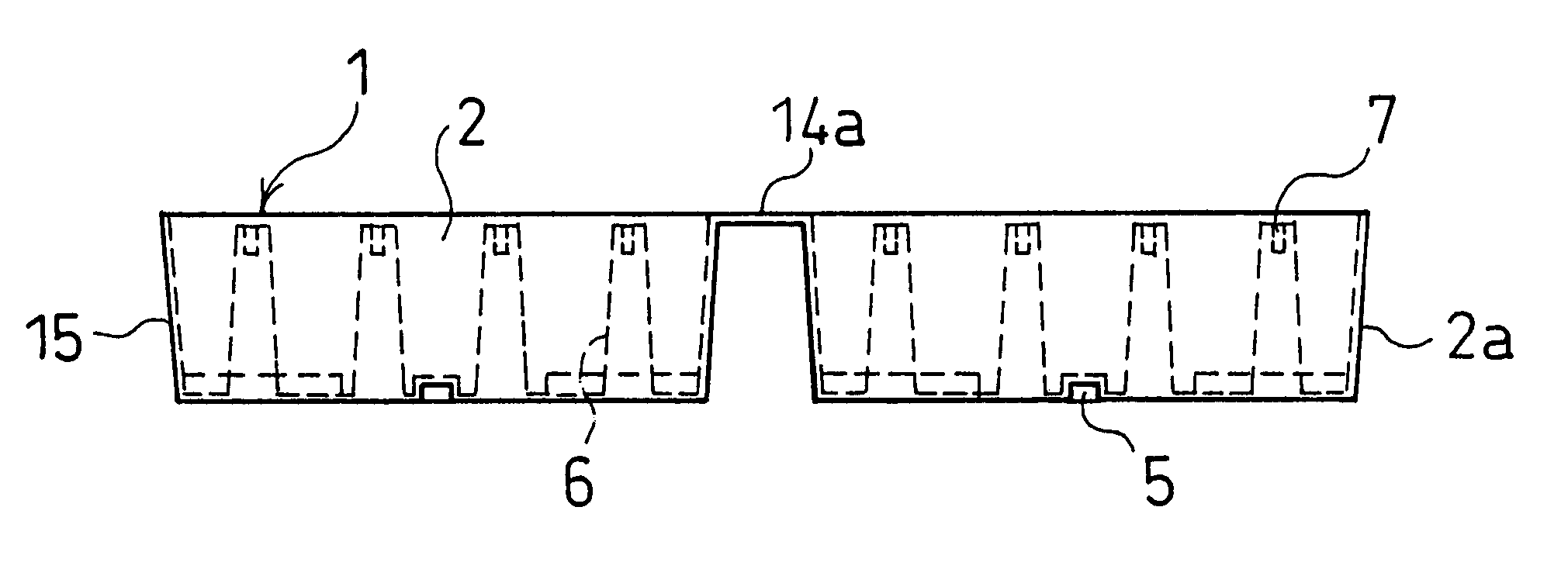
Next, explanations will be given as to an embodiment, wherein a plurality of cells 2 are mutually joined together to construct a plant cultivation mat 1 as an integral whole. FIGS. 9 to 11 illustrate the plant cultivation mat 1 according to the present invention, as outlined above, wherein a plurality of substantially square-shaped cells 2 are disposed in a recessed form, the adjacent cells 2 being joined together through a connecting rib 14a by their upper end parts to constitute a single square mat frame 15.
A peripheral rib 14b having a height which is the substantially same as that of the connecting rib 14a is provided on the upper end part of the lateral wall 2a of the cell 2 surrounding the outer peripheral part of the mat frame 15. Similarly to the afore-mentioned second embodiment, the mat frame is provided, in and on the bottom surface 2b of each cell 2, with the water-passage port 4, the downwardly open part 5, and a plurality of independent pillar member 6.
Thickness of the...
PUM
 Abstract
Description
Claims
Application Information
 - R&D
- Intellectual Property
- Life Sciences
- Materials
- Tech Scout
- Unparalleled Data Quality
- Higher Quality Content
- 60% Fewer Hallucinations
Browse by: Latest US Patents, China's latest patents, Technical Efficacy Thesaurus, Application Domain, Technology Topic, Popular Technical Reports.
© 2025 PatSnap. All rights reserved.Legal|Privacy policy|Modern Slavery Act Transparency Statement|Sitemap|About US| Contact US: help@patsnap.com


