High pressure rotary shaft sealing mechanism

Inactive Publication Date: 2001-05-08
KALSI ENG
View PDF12 Cites 118 Cited by
  • Summary
  • Abstract
  • Description
  • Claims
  • Application Information

AI Technical Summary

Benefits of technology

It is another feature of the present invention to provide a laterally translatable rotary shaft sealing mechanism having the capability for accommodating wide assembly clearances and bearing internal clearances in condition of large diameter rotary shaft sealing, which can permit large dynamic runout and lateral offset of the shaft, and which can also cause large variations in shaft to housing clearance.
It is an even further feature of the present invention to provide a laterally translatable rotary shaft sealing mechanism that is capable of accommodating conditions of enhanced dynamic runout and housing pressure breathing while effectively minimizing pressure responsive seal extrusion and thereby providing for extensive service life of the rotary shaft seals thereof.
Briefly, the present invention is a laterally translatable pressure staged rotary shaft sealing mechanism which is an improvement over the hydraulic force balanced, laterally translating rotary seal carrier assembly of commonly assigned U.S. Pat. No. 5,195,754. The invention provides laterally translatable seal annular carrier means which are laterally translatable relative to a housing having a shaft passage exposed to a pressure therein, and provides staging pressure means which divides a fluid pressure across two or more annular resilient rotary sealing elements by introducing a staging pressure into staging pressure chamber(s) located between the two or more annular resilient rotary sealing elements, and also incorporates a fluid circulation system to provide active seal cooling means and bearing cooling means. A force balancing system substantially balances the hydraulic forces acting axially on the laterally translatable seal annular carrier means, thereby assuring freedom of lateral translation. In several embodiments, the force balancing system establishes substantial balancing of radially acting hydraulic forces such that the axially hydraulic force balanced laterally translatable seal carrier means are made substantially immune to pressure breathing. The invention provides enhanced rotary seal extrusion resistance, higher pressure capability, and better compatibility with rotary seal hydrodynamic lubrication, compared to prior art.

Problems solved by technology

A particularly difficult sealing situation occurs when a housing containing high pressure fluid is penetrated by a relatively rotatable shaft of large diameter.
The difficulty is compounded when available axial space for the shaft sealing mechanism is limited.
If the shaft to housing clearance is too large, the pressure causes the seal to bulge or protrude into the shaft to housing clearance and suffer classic extrusion damage leading to early failure.
Cyclic strain causes the protruding material to break away from the seal, only to be replaced by more protruding material until the seal ultimately fails.
If shaft to housing contact occurs, the housing assumes part of the side load intended for other bearing locations, and the resulting friction and heat can damage the shaft and housing and destroy the rotary seal.
Unfortunately, if the shaft to housing clearance for a large shaft is in a useful range for resilient rotary seals, it is virtually impossible to guide the shaft so precisely that it will not rub on the housing bore.
A number of factors prohibit a small shaft to housing clearance and precise shaft guidance in large machinery.
Manufacturing tolerances are large, which directly affects the size of shaft to housing clearance, and also increases bearing mounting clearance and bearing internal clearance, which permits shaft runout and misalignment.
Large components are often subject to significant elastic deformation when exposed to high pressure and large mechanical loads, and are often subject to significant dimensional variability from differential thermal expansion and contraction caused by seal and bearing heat.
Such dimensional variability can have a dramatic effect on assembly clearances and bearing internal clearances, which can permit large dynamic runout and lateral offset of the shaft, and which can also cause large variations in shaft to housing clearance.

Method used


Image

  • High pressure rotary shaft sealing mechanism
  • High pressure rotary shaft sealing mechanism
  • High pressure rotary shaft sealing mechanism

Examples


Embodiment Construction

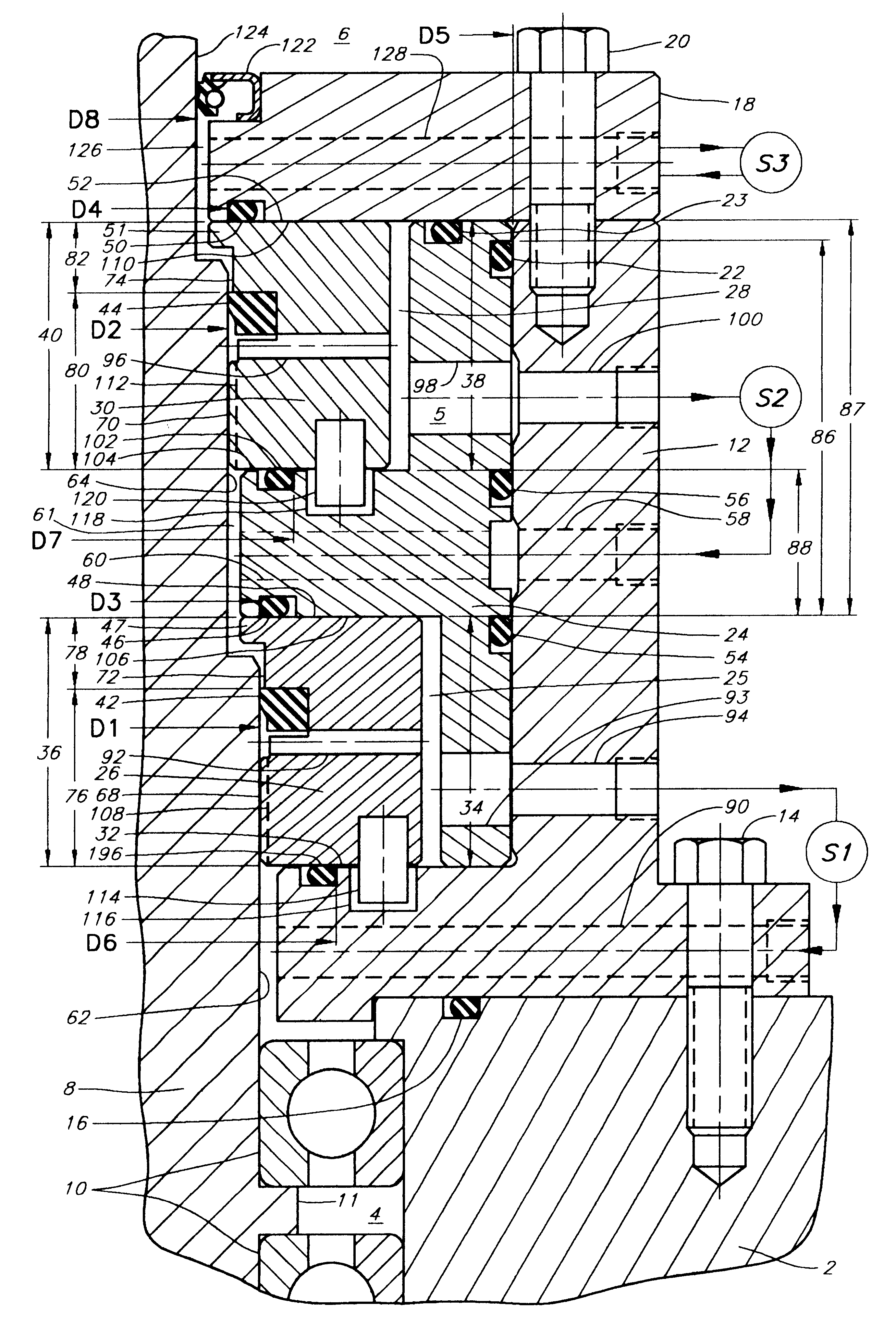
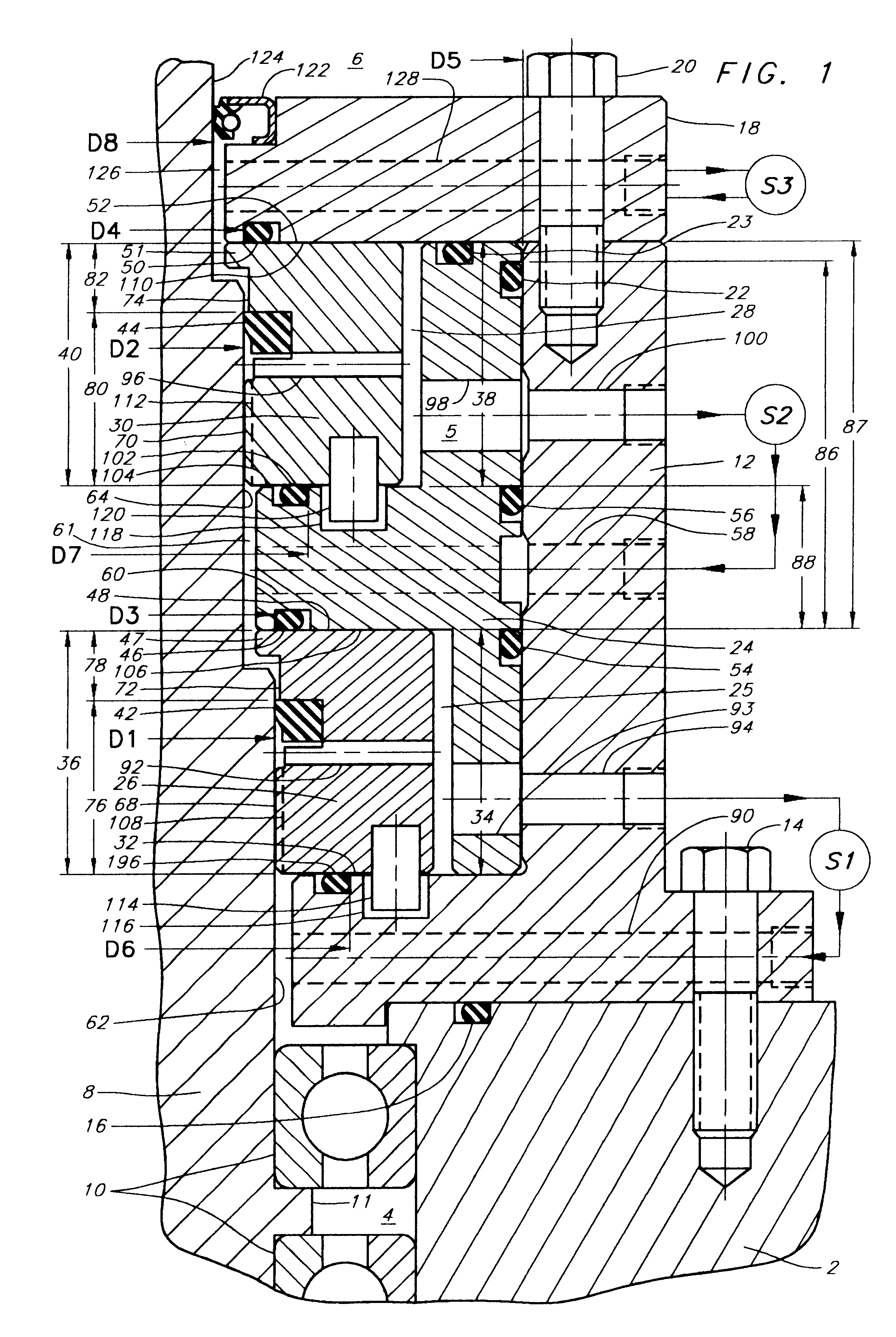
Referring now to the Drawings and first to FIG. 1, the invention is a shaft sealing mechanism which provides axially hydraulic force balanced laterally translatable seal carrier means, and provides staging means which divides a fluid pressure across two or more rotary seals, and also provides active seal cooling means and bearing cooling means, and provides enhanced rotary seal extrusion resistance, higher pressure capability, and efficient compatibility with rotary seal hydrodynamic lubrication.

The Embodiment of FIG. 1

The invention, represented in fragmentary longitudinal cross-section in FIG. 1 herein is a laterally translatable pressure staged rotary shaft sealing mechanism directed at fluid retention in applications where a relatively rotatable shaft penetrates a housing or vessel containing a pressurized fluid therein. The invention is particularly suitable for use where the shaft may have dynamic runout and side-load induced shaft lateral offset, such as when large diameter sh...


PUM


Abstract

A laterally translatable pressure staged rotary shaft sealing mechanism having a seal housing with a shaft passage therein being exposed to a fluid pressure P1 and with a rotary shaft being located within the shaft passage. At least one annular laterally translatable seal carrier is provided. First and second annular resilient sealing elements are supported in axially spaced relation by the annular seal carriers and have sealing relation with the rotary shaft. The seal housing and at least one seal carrier define a first pressure staging chamber exposed to the first annular resilient sealing element and a second pressure staging chamber located between and exposed to the first and second annular resilient sealing elements. A first fluid is circulated to the first pressure chamber at a pressure P1, and a second staging pressure fluid is circulated to the second pressure chamber at a fraction of pressure P1 to achieve pressure staging, cooling of the seals. Seal placement provides hydraulic force balancing of the annular seal carriers.

Description

1. Field of the InventionThe present invention relates generally to laterally translatable seal carrier mechanisms having rotary shaft seals. More particularly, the present invention is directed to an axially hydraulic force balanced laterally translatable seal carrier mechanism having a pressure staging system which divides a fluid pressure across two or more rotary shaft seals and also provides for active seal cooling and bearing cooling. In several embodiments, the axially hydraulic force balanced laterally translatable seal carrier system is substantially immune to pressure breathing. The invention also provides for enhanced rotary seal extrusion resistance, high operating pressure capability, and compatibility with rotary seal hydrodynamic lubrication.2. Description of the Prior ArtA particularly difficult sealing situation occurs when a housing containing high pressure fluid is penetrated by a relatively rotatable shaft of large diameter. The difficulty is compounded when avai...

Claims


Application Information

Patent Timeline
IPC IPC(8): F16J15/00F16J15/16F16J15/32F16J15/54E21B4/00
CPCE21B4/003F16J15/006F16J15/166F16J15/324F16J15/54
Inventor DIETLE, LANNIEGOBELI, JEFFREY D.
Owner KALSI ENG
Why Eureka
Try Eureka