
Instrumentation system and method including an improved driver software architecture

a software architecture and instrumentation system technology, applied in the direction of instruments, fluid pressure measurement, software simulation/interpretation/emulation, etc., can solve the problems of insufficient number of commands for covering all the different types of instruments, difficult and time-consuming, tedious acquisition and analysis of data in such instrumentation systems

Inactive Publication Date: 2001-04-24
NATIONAL INSTRUMENTS
View PDF8 Cites 42 Cited by
  • Summary
  • Abstract
  • Description
  • Claims
  • Application Information

AI Technical Summary

Problems solved by technology

Acquisition and analysis of data in such instrumentation systems was tedious and error prone.
Therefore, implementation of such systems frequently requires the involvement of a programmer to develop software for acquisition, analysis and presentation of instrumentation data.
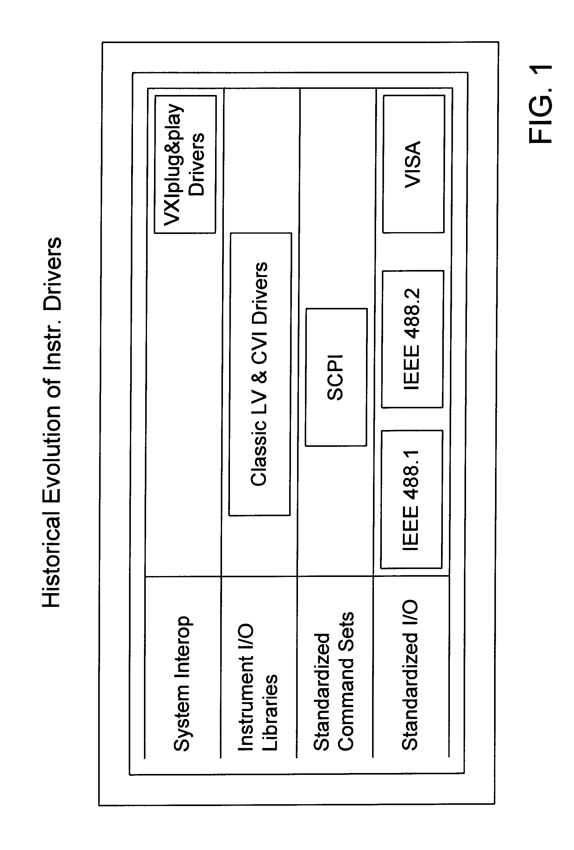
However, each of these libraries generally still required the user to understand command strings and / or what registers were required to peek and poke within an application to control an instrument.
However, SCPI did not provide a sufficient number of commands to cover all the different types of instruments available.
These instrument drivers encapsulate all of the low level syntax and the order of operation that is required to send commands to an instrument, which can be very difficult and time consuming.
However, the VXIplug&play instrument drivers did not address other high level system issues, such as state caching, simulation and instrument interchangeability, among others.
A primary problem with the traditional software architecture for an instrumentation system is that a separate instrument driver is required for each specific instrument.
If one or more fundamental attributes which will affect instrument behavior in the current configuration are not in a user-specified state, the class driver records an error.
However, this does not provide the replacement and re-usability benefits of the present invention.
In general, whenever the user sets an attribute, this can cause the state of another attribute to become unknown.
If the deferred update attribute is set to true when the set attribute function in the IVI engine is called and a deferred update is already pending for that attribute, the set attribute function returns an error.
An error would occur if a user application started using a specific driver with a different set of discrete values.

Method used


Image

  • Instrumentation system and method including an improved driver software architecture
  • Instrumentation system and method including an improved driver software architecture
  • Instrumentation system and method including an improved driver software architecture

Examples


Embodiment Construction

.INI File

[IviLogicalNames]

Scope1="VInstr->TekTDSC"

[Class->IviScope]

Description="IVI Digital Oscilloscope Class Driver"

Simulation VInstr="VInstr->NISimOsc"

[VInstr->TekTDSC]

Description="Tektronix TDS 754A / C"

Driver="Driver->TekTDSC"

Hardware="Hardware->TekTDSC"

Simulate=False

UseSpecificSimulation=False

RangeCheck=False

QueryInstrStatus=False

Cache=True

Spy=True

RecordCoercions=False

InterchangeCheck=False

DefaultSetup="DefaultSetup->TekTDSC"

VirtualChannelNames="a=ch1,b=ch2"

ChannelListSelector=""

[Driver->TekTDSC]

Description="Tektronix TDS 754A / C Driver"

ModulePath="tktds754.dll"

ChannelList=""

Prefix="tktds754"

[Hardware->TekTDSC]

Description="Tektronix TDS 754A Digital Oscilloscope"

ResourceDesc="GPIB::2::INSTR"

[DefaultSetup->TekTDSC]

CHANNEL_ENABLED True

Deferred Updates

When a high-level driver function in the Specific Driver 308 makes multiple calls to the Ivi SetAttribute functions in the IVI Engine 306, it can postpone the actual transmission of the new attribute values to the instrument. It can la...


PUM


Abstract

A system and method for controlling an instrumentation system, wherein the present invention includes an improved instrument driver software architecture. The instrument driver software architecture of the present invention provides a number of features, including instrument interchangeability, i.e., the use of interchangeable virtual instruments or interchangeable instrument drivers, improved performance, an improved attribute model, improved range checking, and improved simulation features, among others.

Description

The present invention relates to instrument driver software for instrumentation systems, and more particularly to an instrumentation driver software architecture for communicating with and controlling instruments in an instrumentation system.DESCRIPTION OF THE RELATED ARTAn instrument is a device which collects data or information from an environment or unit under test and displays this information to a user. An instrument may also perform various data analysis and data processing on acquired data prior to displaying the data to the user. Examples of various types of instruments include oscilloscopes, digital multimeters, pressure sensors, etc., and the types of information which might be collected by respective instruments include voltage, resistance, distance, velocity, pressure, frequency of oscillation, humidity or temperature, among others.In the past, many instrumentation systems comprised individual instruments physically interconnected with each other. Each instrument typica...

Claims


Application Information

Patent Timeline
IPC IPC(8): G06F7/00G01C25/00G01D18/00
CPCG06F9/455
Inventor RUST, SCOTTBELLIN, JONGREY, JAMES
Owner NATIONAL INSTRUMENTS
Learn More