
Truck bed extender

a technology for extending devices and trucks, which is applied in the direction of roofs, transportation items, loading/unloading vehicle arrangments, etc. it can solve the problems of not being able to use the tailgate top for support, not being able to easily disassemble or break down to fit within the tool box, and not being able to easily fold or cross-brace construction, etc., to achieve the effect of easy disassembly and folding within the toolbox

Inactive Publication Date: 2001-04-10
BOHANNON JERRY W
View PDF25 Cites 16 Cited by
  • Summary
  • Abstract
  • Description
  • Claims
  • Application Information

AI Technical Summary

Benefits of technology

(2) The cross-bracing is easily installed and replaced for different width vehicles.
(5) The device is easily disassembled and foldable within a toolbox.

Problems solved by technology

While it folds, it does not easily assemble or break down to fit within a tool box nor does it fit within the "Stake Socket" of the truck.
This construction is also not easily folded or cross-braced, and does not use the tailgate as a support.
They also fail to use the tailgate top for support.
The Schmeets U.S. Pat. No. 5,775,655 shows a foldable table but fails to add to the art of the rack systems.
None of the prior art utilized the top of the tailgate as well as the extension or as well as an extended surface to provide a support.

Method used


Image

  • Truck bed extender
  • Truck bed extender
  • Truck bed extender

Examples


Embodiment Construction

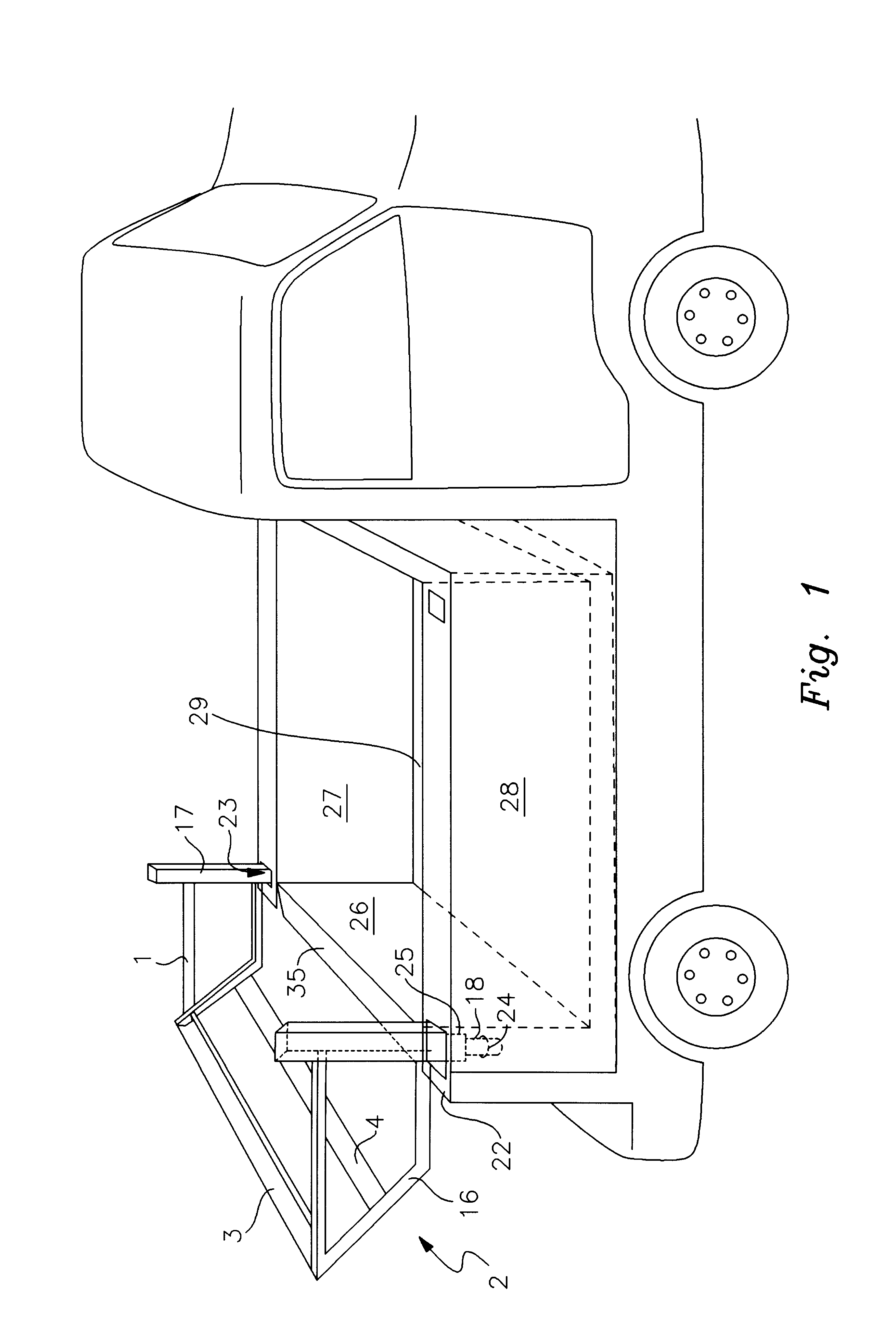
As can best be seen in FIG. 1, a typical truck for which this would be used has a truck bed having a left side panel 27 and a right side panel 28 which hold a tailgate 26. Within these is the truck bed 29.

Both the left side panel 27 and the right side panel 28 define a side wall chamber 23 which is a small chamber designed to receive a rack which can be mounted on most model trucks.

Between the chamber 23 and very rear of the truck is the back 22 of the side wall.

The present invention is a rack designed to work off of and fit within the side wall chamber 23 so that lumber, ladders or other long equipment may be carried on a tailgate which is not long enough to accommodate the load in the truck bed 29.

The load is elevated to the height of the top 35 of the tailgate 26. In this way, the load is supported by the truck bed 29, the top 35 of the tailgate 26 and by the contact wall 55 of the top cross bar 3.

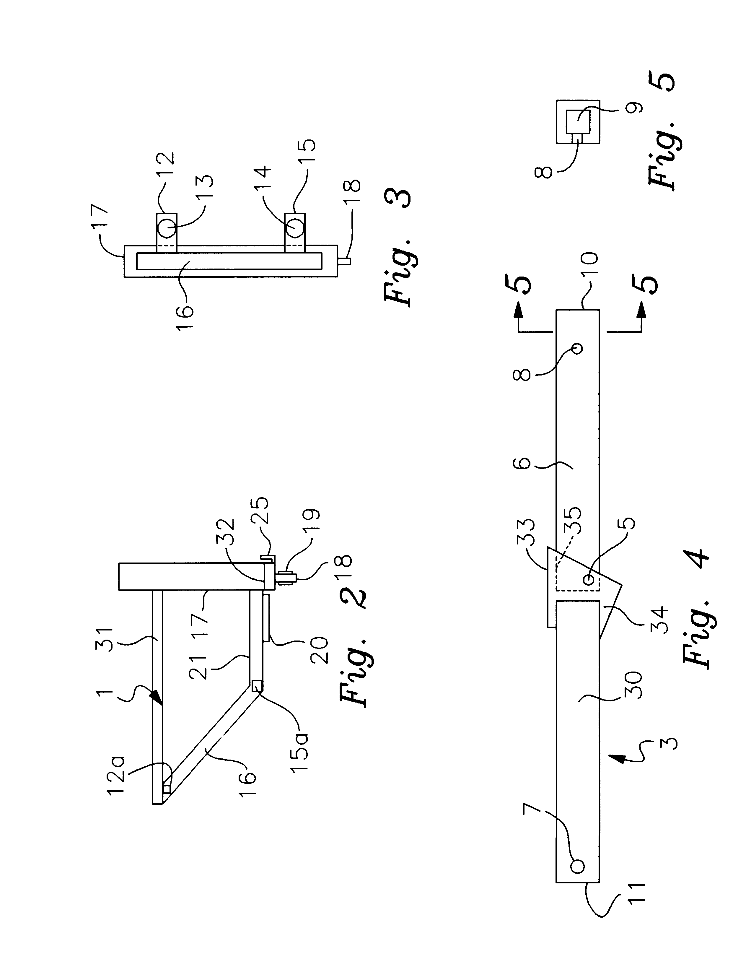
A left frame 1 and right frame 2 support the top and bottom cross bars 3 and 4. FIG...


PUM


Abstract

An auxiliary load supporting apparatus for a vehicle having a front and a rear and a left and right sidewall, comprising: a first base mounted to said left sidewall and extending upward therefrom to a desired height, between six inches and 50 inches above said left sidewall; a second base mounted to said right sidewall and extending upward therefrom to a desired height, between six inches and 50 inches above said right sidewall; a first framework mounted to said first base and extending rearward therefrom away from the left sidewall; a second framework mounted to said second base and extending rearward therefrom away from the right sidewall; a transom extending from the first framework to the second framework rearward from the rear. A third support point is defined by the angle between the transom and the truck bed by the tailgate of the truck so that the transom does not need to take all of the support of the load.

Description

BACKGROUND OF INVENTION1. Field of InventionThe invention pertains to truck bed extending devices. More particularly the invention describes an extension attachable to the rear of a truck allowing the weight of an article carried to be borne by the extended transom and the top of the truck tailgate.2. Prior ArtThe Lowe U.S. Pat. No. 5,743,583 shows a rack system fitting above the truck and in front of the tailgate. Loads may be carried above the vehicle. The design suggests that the rack itself is to support the weight independently. While it folds, it does not easily assemble or break down to fit within a tool box nor does it fit within the "Stake Socket" of the truck.The Cumbie U.S. Pat. No. 5,120,102 shows a load bearing extension requiring a trailer hitch. A hook assembly does not support the unit which uses the receiver hitch 42-44-48 for support but does prevent the unit from falling. The unit is designed to extend the bed, but does not utilize the top of the tailgate or a cus...

Claims


Application Information

Patent Timeline
Patent Type & Authority Patents(United States)
IPC IPC(8): B62D33/02B60P3/40B62D33/023
CPCB60P3/40B62D33/023
Inventor BOHANNON, JERRY W.
Owner BOHANNON JERRY W
Learn More