Eureka AIR delivers breakthrough ideas for toughest innovation challenges, trusted by R&D personnel around the world.

Device for attaching an engine to an aircraft strut

a technology for aircraft engines and struts, which is applied in the direction of machine supports, transportation and packaging, and other domestic objects, can solve the problems of affecting aircraft safety, connection is not able to meet new demands, and the integrity of the overall attachment device is doubted, so as to achieve reliable and durable effects

Inactive Publication Date: 2001-04-03
SOC NATIONALE INDUSTRIELLE AEROSPATIALE SA
View PDF6 Cites 27 Cited by
  • Summary
  • Abstract
  • Description
  • Claims
  • Application Information

AI Technical Summary

Benefits of technology

is to solve in a reliable and durable manner the safety problems caused by existing aircraft engine attachment devices, but without leading to any modification to the engines.
In other words, the object of the invention is an aircraft engine attachment device, whose original design enables it to maintain its integrity and consequently does not bring into doubt the safety of the aircraft, in the case of a failure of any one of its components, without it being necessary to add a supplementary connection to the two connections normally connecting the fitting to the engine.
Moreover, the holding part integrated into each of the two connections between the fitting and the engine, ensures the redundancy of these connections.

Problems solved by technology

As a result of the monolithic or one-piece character of the fitting and the attachment parts, a failure of any random one of these parts is liable to cast into doubt the integrity of the overall attachment device, thus seriously affecting aircraft safety.
However, it does function when any random element of said device fractures.
Firstly, the supplementary connection is not generally dimensioned in order to comply with the regulations, which require such a connection to be able to function in a completely satisfactory manner for thousands of flying hours corresponding to the inspection interval defined by said regulations for the aircraft in question.
Moreover, this solution requires the provision of a third attachment point on the engine, which leads to a modification of the latter.
Thus, this connection is unable to comply with new demands laid down by the certification authorities in connection with the integrity of the device.

Method used


Image

  • Device for attaching an engine to an aircraft strut
  • Device for attaching an engine to an aircraft strut
  • Device for attaching an engine to an aircraft strut

Examples


first embodiment

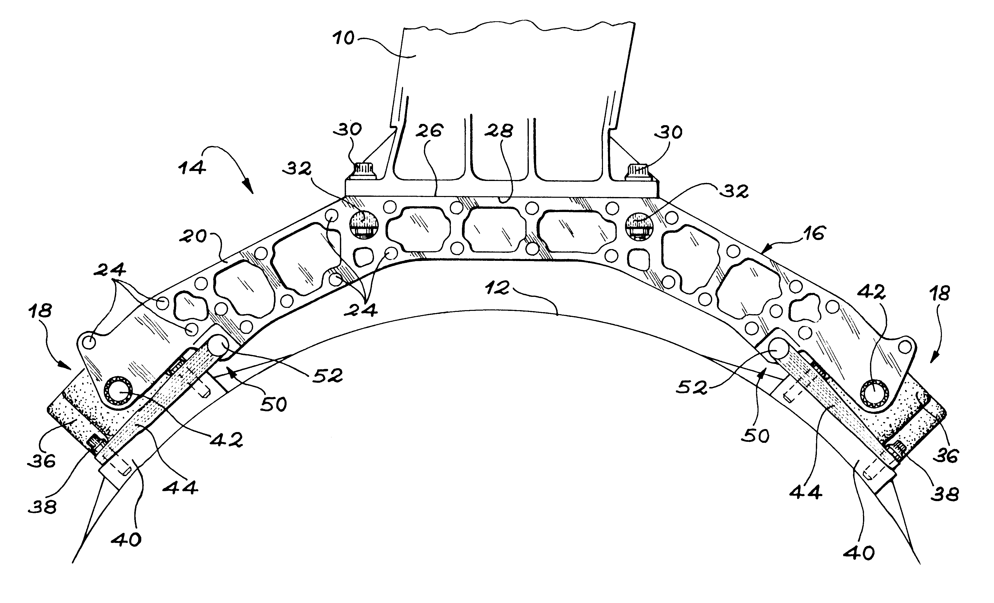
FIG. 1 A front view of an aircraft engine attachment device in the invention.

FIG. 2 A view from below and in perspective of the right-hand half of the device of FIG. 1.

FIG. 3 A top view, in perspective, showing the left-hand half of the device of FIG. 1.

second embodiment

FIG. 4 A fragmentary front view illustrating the device according to the invention.

FIG. 5 A cross-sectional view along line V--V of FIG. 4.

FIG. 6 A view comparable to FIG. 4, illustrating a variant of the second embodiment of the invention.

FIG. 7 A cross-sectional view along line VII--VII of FIG. 6.

FIG. 8 A view comparable to FIGS. 4 and 6 illustrating another variant of the second embodiment of the invention.

FIG. 9 A cross-sectional view along line IX--IX of FIG. 8.


PUM


Abstract

A device (14) for attaching or hooking an engine to an aircraft strut (10) comprises a circular arc-shaped fitting (16), formed from two elementary, coupled portions, which are also circular arc-shaped. These two elementary portions can be separate parts joined by bolts (24). The fitting (16) is fixed to the strut (10) by tension screws (30) and is solely connected to the engine by two connections or links (18). Each of these connections comprises a damping or shock absorber block (36) fixed to a base (40) connected to the engine and connected to one end of the fitting by a spindle (42). A holding part (44), fixed between the shock absorber block (36) and the base (40), is connected to the fitting by a joint (50) with clearance.

Description

DESCRIPTION1. Technical FieldThe invention relates to a device for attaching or hooking an aircraft engine to a strut fixed to a structure of the aircraft, such as a wing or a fuselage element.More specifically, the invention relates to an attachment device for absorbing or taking up lateral and vertical thrust forces and the torque produced by the engine and which must be retransmitted to the aircraft by means of the strut.2. Prior ArtEach of the engines is suspended or attached in lateral manner to a strut, which is itself respectively fixed beneath the wing or to the aircraft fuselage.The attachment systems connecting engines to struts are generally formed from two or three separate attachment devices. One of these devices is responsible for taking up the lateral and vertical thrust forces and the engine torque, which are produced by the engine, in order to retransmit them to the aircraft by means of the strut.In the prior art, the attachment devices responsible for the taking up...

Claims


Application Information

Patent Timeline
Patent Type & Authority Patents(United States)
IPC IPC(8): B64D27/26B64D27/00
CPCB64D27/26B64D2027/266B64D27/40B64D27/404
Inventor LE BLAYE, SEBASTIEN
Owner SOC NATIONALE INDUSTRIELLE AEROSPATIALE SA
Why Eureka
Eureka Blog
Learn More