Constant velocity universal joint for therapy devices
a technology of constant velocity and therapy devices, applied in the field of constant velocity universal joints for therapy devices, can solve the problems of general population suffering from bodily injuries, athletes, both weekend and professional, and athletes prone to injury during a variety of activities
- Summary
- Abstract
- Description
- Claims
- Application Information
AI Technical Summary
Benefits of technology
Problems solved by technology
Method used
Image
Examples
embodiment 1
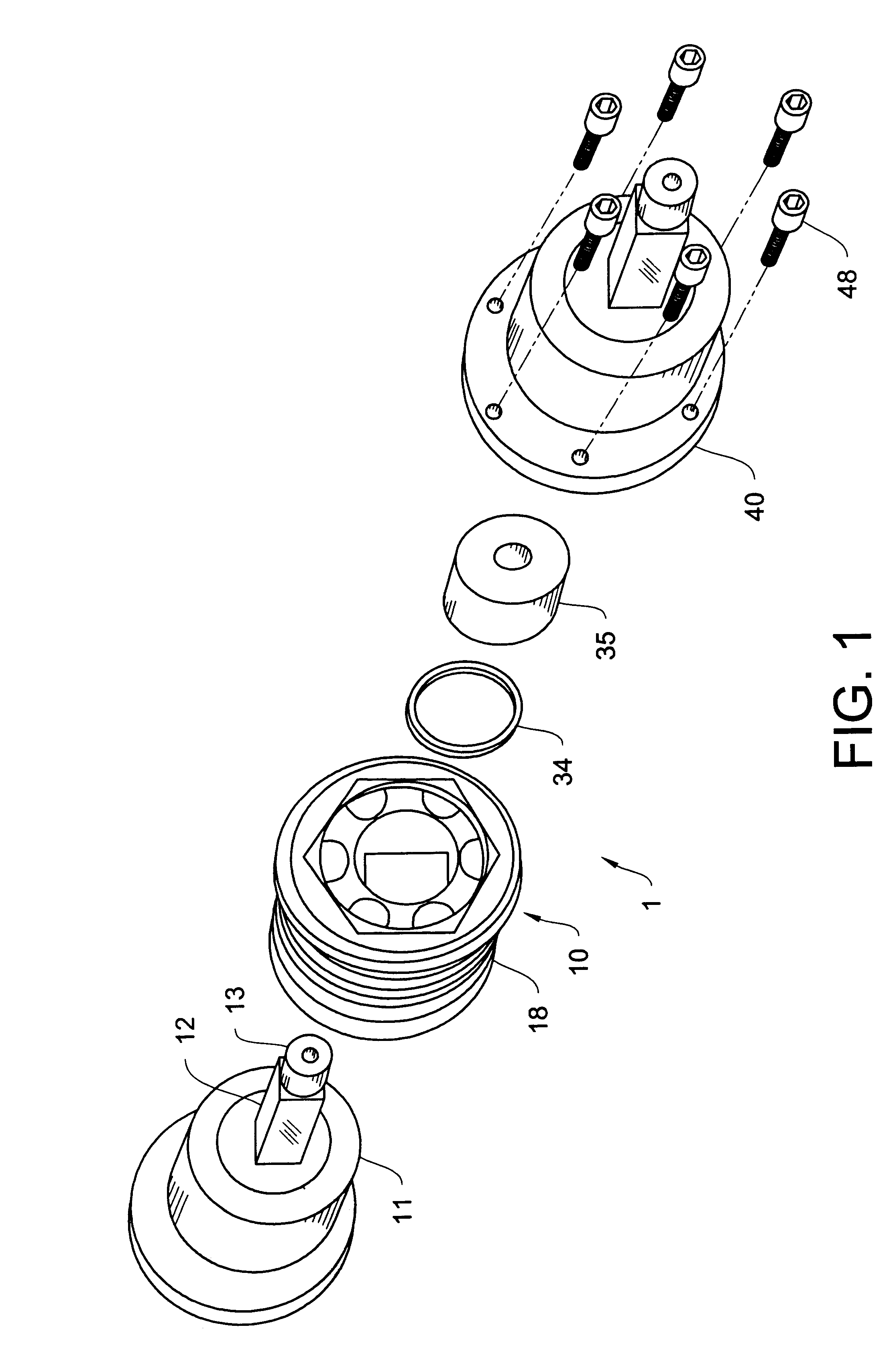
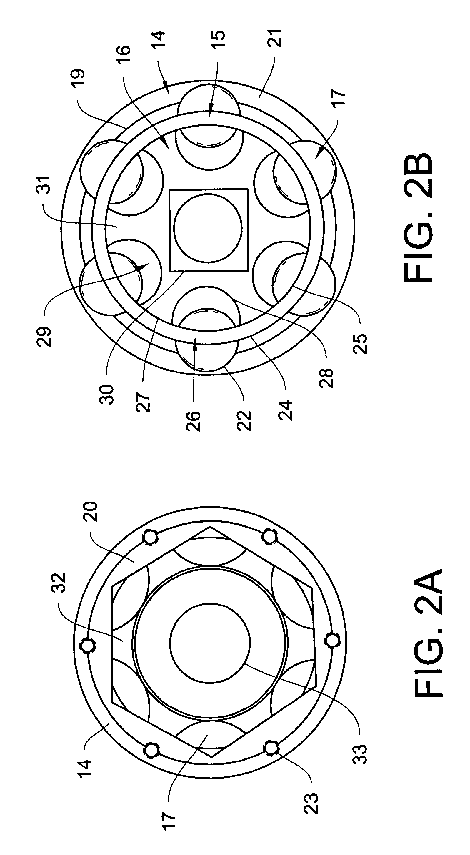
A first preferred embodiment 1 of the present invention is constructed from a first major piece 10, a universal joint and a second major piece 40, an attachment adapter cap. The universal joint 10 is typically secured to a conditioning / rehabilitation / testing apparatus attachment shaft 11, located on, or within, an apparatus such as a dynamometer. The attachment adapter cap 40 is then secured to the universal joint. An alternate form of the device of the present invention utilizes an attachment adapter cap 40 that is integrally formed onto the universal joint 10. The device then secures onto the conditioning / rehabilitation / testing apparatus through threaded means or other equivalent securing structures.
In the first preferred embodiment, the apparatus attachment shaft 11 consists of a square shaft portion 12 having a distal end, said square shaft portion 12 projecting from an exterior surface of the apparatus. Located at the distal end of the square shaft portion 12 of the apparatus a...
embodiment 2
A second preferred embodiment 2 utilizes the same universal or constant velocity universal joints 10 as the first preferred embodiment. The second preferred embodiment has a first major section 60, a second major section 70, and a third major section 80. The second major section 70 is the universal or constant velocity universal joint, preferably a constant velocity universal joint as described above in the first preferred embodiment.
The first major section 60 of the second preferred embodiment is an adapter matching insert 60. The adapter matching insert 60 is formed to fit a apparatus attachment receiver 50. In the second preferred embodiment 2, the adapter matching insert 60 is constructed starting with a square tubular section 61. Secured to a first end 62 of the square tubular section 61 is an insert spacer 63 that projects at a first end 64 of the insert spacer 63 over one side of the square tubular section 61. The insert spacer 63 is connected at a first end 64 of the insert ...
first embodiment
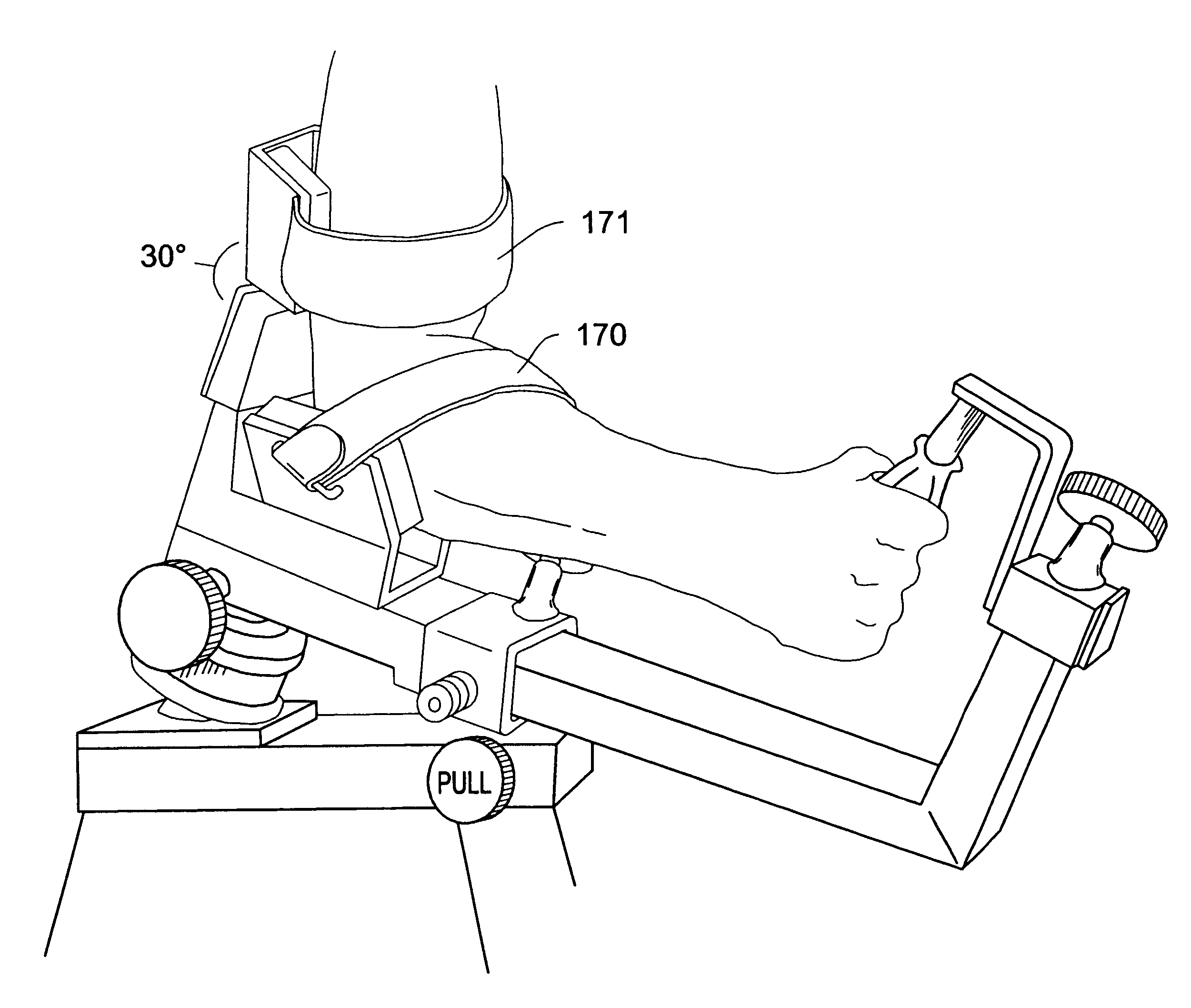
The upper arm support structure 151 comprises an adjustable attachment section 154 which is secured to the second end 84 of the square tubular section 81 of the second preferred embodiment. The adjustable attachment section 154 has a pair of padded angled elbow rests 155 which support the user's elbow during use. Attached to the adjustable attachment section 154 is a support arm 156 attached a approximately a 30 degree angle with a V or U shaped upper arm support 157 located at a distal end thereof. As in the first embodiment, the approximate 30 degree angle of the support arm 156 provides comfort to the user in addition to physical support. The upper arm support 157, like the pair of elbow rests 155, is also padded.
The second lever arm 152 of the second apparatus attachment 150 is of square tubular construction and is adjustably received within the adapter matching attachment receiver 80. There is a perpendicular section 158 located at a distal end 159 of the second lever arm 152. ...
PUM
 Abstract
Description
Claims
Application Information
 - R&D
- Intellectual Property
- Life Sciences
- Materials
- Tech Scout
- Unparalleled Data Quality
- Higher Quality Content
- 60% Fewer Hallucinations
Browse by: Latest US Patents, China's latest patents, Technical Efficacy Thesaurus, Application Domain, Technology Topic, Popular Technical Reports.
© 2025 PatSnap. All rights reserved.Legal|Privacy policy|Modern Slavery Act Transparency Statement|Sitemap|About US| Contact US: help@patsnap.com


